

bkbrowning
-
Posts
22 -
Joined
-
Last visited
Content Type
Events
Profiles
Forums
Everything posted by bkbrowning
-
LoveMonkey - Sorry for belated reply. My shells are 8cm in length. Shout if you need anything else. -brent
-
Nick and Team - I did as much research as I could on Pack #4 and its associated frame. For some screenie comparisons, please see my build thread at http://forum.mepd.net/index.php?showtopic=13944 as I don't believe that it was a typical ALICE style frame. I'd certainly like to know for sure what it was, but the ALICE frame just seems to be off from the screen shot details that we can pick out. Got to love a hobby where we can still debate details 37 years after they were published. Let's keep it rolling until the truth is known. Thanks! -brent
-
I brought mine...That's me in the picture smiling behind my bucket on the right. A few interesting tidbits: 1) I scared and impressed the cabin cleaning crew when I emerged from my stateroom in my TD. Lots of fun and pictures ensued. They were thrilled. 2) I was "reminded" by a ship officer out in the lobby that I "should have received a note regarding wearing of helmets and masks in public areas. We don't want any of our guests to be confused and think that you are part of the Disney cast." He was polite about it. I was about to ride an elevator down a floor and told him I would remove it then. Once I got there, a large line formed of guests wanting to take pictures so I ended up leaving the helmet on for quite some time and just stayed in one place. Once everyone had their fill of pictures, I pulled the helmet as asked. When others came up wanting a picture, I just put it back on for those. All-in-all, the ship's crew was polite. I got the feeling that they didn't want to interrupt the other guests photo ops to ask me to take it off. 3) A 501st guest in an impeccable imperial officer uniform gave me a dressing down about the state of my armor being filthy. He did it when we were both surrounded by guests. I replied about the harsh assignment on tatooine, rebel disruption of our supply line, and the need for additional reinforcements. It made for a spirited exchange in front of a lot of guests who were laughing and enjoyed the role playing. 4) Hot and moist Caribbean air does not go well with a full TD suit. :-) It was NOT a dry heat. From the 501st, I met one Biker Scout and one other plain TK that both brought their armor kit. There were several other 501st members on board...many of which were imperial officers, dark side force users. Also, a good showing from the Rebel Legion with lots of Jedi, a few X-Wing pilots, Leia (princess and one slave outfit), etc. For Disney, they had two Royal Guard roaming the ship that day. Two TKs that were mostly posing for pictures. Some Jawas that would trade items with you (they were really well done). Imperial officers, bounty hunters, rebel pilots, random jedi, R2-D2, C3PO, Chewbacca and Lord Vader were also present throughout the day. While we were on our cruise, Disney announced that they are offering 15 Star Wars cruises for 2017. Ours was #5 of 8 for 2016. It was a great cruise. The Star Wars day was a LOT of fun with great interaction throughout the day. Nice to be with so many fans. Shout if you have other questions.
-
For Christmas my wife surprised me with a Star Wars Disney cruise. We just left the ship but had a great time with thousands of Star Wars fans and over two dozen 501st members. Here's a quick look at the rest of my family garrison...still trying to sway them from the Rebel legion! Had a great time and Disney made it a great day of Star Wars fun for all ages. And, for those that are wondering...I'm slowly working my way to my PO application. Will try to get it underway shortly.
-
RT-97C build from real MG15
bkbrowning replied to bkbrowning's topic in T-21, DLT-19, RT-97c Heavy Blasters
One more quick update: with the help of some large pipe wrenches, we were able to get the barrel and heat shield free from my original MG15! As such, it's now gone from my RT-97C and looks much more like the movie version. I think I'm finally happy with it...and yes, I am smiling in the pic below! -
RT-97C build from real MG15
bkbrowning replied to bkbrowning's topic in T-21, DLT-19, RT-97c Heavy Blasters
Desert Rat - Looking at all the options for the mounting bracket for the InfraRed scope, I personally decided to go with one that was modeled after the RT-97C "blueprints" from the Star Wars Blueprints: The Ultimate Collection book (link to Amazon's listing). In that set of blueprints, there is a 75% wireframe sketch of this BFG and the bracket looks like it is offset from the main body of the rifle and attached to two rings that wrap the end of the scope. Here is the page from the blueprints themselves. Sorry that it's so small but I had to copy it from a reference on the web. When I get back home from being out of town, I'll shoot a picture of that section of the blueprints and upload them here. Also, the original sketch for this book was drawn by Chris Trevas and Chris Reiff (I think that's correct spellings) and their art for this also shows this in some detail here: Hope that helps. Shout back if you want more pictures of my build or need anything else. -
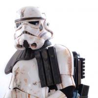
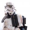
If you haven't see this shot yet, you should head on over to http://www.wired.co.uk/news/archive/2015-11/18/star-wars-force-awakens-stormtrooper-dressing-room There are some really cool pictures of the new EPVII armor. All we need now is a ***lot*** of burnt umber paint and we could fix those right up.
-
RT-97C build from real MG15
bkbrowning replied to bkbrowning's topic in T-21, DLT-19, RT-97c Heavy Blasters
I ***think*** I may be able to separate the barrel without having to cut it and still be able to keep the ventiliation cage, barrel cap, and front end of the receiver housing held together. The barrel itself is a key structural part of holding all those components in place...but I think we can rig it up. What looks like one piece does show as separable based on some parts research that I've now done. Unfortunately, after 50+ years of sitting around, it's really, really stuck. Stuck to the point of acting like one piece. I'm taking it to a machine shop on Monday to use some of their tooling and expertise to try and break it apart with minimal damage. Will post some pics after we're done and let you know how we did it. -
RT-97C build from real MG15
bkbrowning replied to bkbrowning's topic in T-21, DLT-19, RT-97c Heavy Blasters
Thanks for the feedback troopers. So, the one question I do have for you all is do you think I should try to remove the inner rifle barrel? It's doable on the MG-15 but does require some destructive cutting to make it happen...not to mention that it will ruin the actual rifle! Reason I ask is that it does appear in nearly all pics that they removed the rifle barrel itself from this weapon for the movies. For instance, see the following pics: All of them (especially the last one...which is the trooper build I'm aiming for) clearly show no inner rifle barrel. So, I'm really thinking about cutting mine out...which is a nutty thing to do to a WWII vintage rifle but it is what I think canon calls for here. Let me know your thoughts. I probably need some encouragement to fire up the metal bandsaw. -
RT-97C build from real MG15
bkbrowning replied to bkbrowning's topic in T-21, DLT-19, RT-97c Heavy Blasters
To finish out, I had only the "infrared" scope to go. I have probably looked through 3,000 images of scopes from the WWII era to try and find what looks like the exact scope used in the movies. While some are close, they seem to all have an issue of some sort. So, I decided to cannibalize a few scope parts and being building my own. For size and scale, I used the reference from the Star Wars Blueprints booklet. Both the scope and the mounting system were custom built from spare parts, PVC, and various metal bits and bolts... I mounted the custom scope rings to the side of the MG15 with some aluminum offsets that would give me the correct angle and height as shown in the blueprints... ..and also mounted the brass pipe fitting to the side to act as a return for the hose coming from this scope. I used a Dremel to contour the profile of the brass fitting to the side of the MG15 and then tapped a set of threads at the appropriate point in the rifle to secure it with a bolt. Assembling and painting a few of the scope parts... I wanted to make sure it had some optics in it, so I used some of those cannibalized parts from other scopes... With the rubber eyepiece and the end scope portion attached, it is looking ready for mounting... And now, all mounted up on the rifle and some light weathering applied. Not too much as, like most troopers, the one thing you'd keep fairly clean would be your weapon! I think that's about it for this build! It's not the lightest weapon, but it does look and feel really good in the hand. Let me know your feedback, questions, comments, or anything that could be improved! -
RT-97C build from real MG15
bkbrowning replied to bkbrowning's topic in T-21, DLT-19, RT-97c Heavy Blasters
Next up is the rear, left side Singlepoint scope. The scope itself is 1" in diameter on the main bore so some 1" scope rings look like they will work just fine. They are designed to clamp onto a scope rail which the MG15 certainly doesn't have down it's left side. So, I modified the scope rings by boring through their center section and created a countersunk spot for the cap-head bolts to attach. I used my tap and die kit to tap the appropriate holes into the MG15 and secure the scope rings. From there, it was straightforward to attach the scope... -
RT-97C build from real MG15
bkbrowning replied to bkbrowning's topic in T-21, DLT-19, RT-97c Heavy Blasters
First thing I wanted to tackle was getting the forward scope mounted to the rifle. The scope of choice here is an Enfield MKII and there's a reticle mounting hole just past the magazine that makes a great mounting point. The only trick was how to rig up the mount. I've seen drawings and some assmeblies that seem to use a curved rod...but it looks like that requires some welding and possibly yields a permanent mount to the Enfield. I was looking for something that could utilize the mounting brace that came with the Enfield and that would be removable for travel. With some careful measurements and a little modeling with Autodesk Fusion 360, I created the following scope mount... To ensure that it would fit, I fired up the 3D printer to create a prototype... Fitting it to the scope using the Enfield's mounting bracket, it fits really well... ...and test mounting to the rifle, it's beginning to look like 1977... The 3D part printed in PLA and printed completely solid is VERY sturdy. I really think I could leave it as-is and not worry about it breaking or coming loose...but...I just had to have it in some type of metal. So, I submitted my 3D model to Protolabs and about 4 days later I had my new solid metal Enfield scope mount... Fully mounted on the weapon, it looks and feels really solid. With a little Aluminum bluing applied, it's looking great on the rifle... -
In addition to my pack and armor build, I've been slowly working on my RT-97C. I managed to pick up an MG15 and a collection of scopes over the past several years and finally began to build out my RT-97C. To start with, here's the base model in all its glory along with some of the scopes...
-
A few of the key details that I was trying to achieve on this Falcon fly away pack... ...the correct frame bends at the top ...what looks like the typical frame bends at the bottom ...the missing top cap on the mortar tube ...the shorter (shortest!) detenator plate ...the white backed radar dish ...the high position on the upside down radio ...the likely wrapping on the outside of the radio ...the mysterious strap across the radio ...genuine tuppercraft box ...the correct number of shotgun shells On that last one, some scenes for this pack seem to show only 4 shells while it looks like 6 are visible in the takeoff scene. To accomodate for that, I 3D printed a mounting plate and inserted some magnet for the top two shells. That way I can attach or detach them as needed. Closeup photo of that here: ...and with the shells magnetically attached... Other features are inside the radio as I put a speaker system in there to play the radio chatter loop. One of the slider switches controls the on/off and one of the knobs is attached to a rheostat to control the volume. Sounds really well (thanks to those that took the time to make the sound loop!) At this point, I think I'm nearly done with this pack. Let me know if you have comments, questions, or things that you think would make it better!
-
Was finally able to put some weathering on my backpack and get a set of near final pictures. Have done the best I could do with the backpack parts that I had (mostly based on a Crashmann kit) to get the spacing right. Here's a side view shot to show the veritcal spacing: And from the top... From left side... And some close ups on the back and strapping...
-
For the straps, I found some 1" wide nylon tie down straps that came with some nice metal buckle/clasps. Just need to figure out a way to securely attach them to the pack frame. To do so, I decided to wrap the straps around the pipe twice and then secure it to the bar with a large rivet. This would allow the majority of the weight to stay on the strap and not on the rivet as it will tend to pull itself tightly to the frame. First, needed to drill the holes for the rivet. I've got some good metal to work with here so it's a nice clean hole that should make a strong rivet mount. With the strap wrapped around twice, you can kind of feel for the hole through the strap. With that as a guide, I used a hot soldering iron to melt a hole through the strap that would match up nicely with the hole below... And then a nice long, thick rivet that will swell up behind that metal frame and secure it nice and tight... Things are looking really good at this point. Just need to take some "final" shots before weathering...which I will do soon and post.
-
With the cross straps attached, it's ready for some test placements. I used some hex head bolts and lock nuts to hold those to the frame. I already had some of the upper items attached to the top lid of the upper seed tray. The rest are just resting to get some test fit and alignment. Attaching the lab pipe and mortar tube as well as the backs of the seed trays. I like to add some metal supports for the rivets through those seed trays. I used the zip tie method to secure the tray tops to the frame. One item to note, the cistern tube needed a wedge that was contoured to the seed tray lid and the angle/position I was looking to mimic. If you look in the reference pictures for this pack, it's hanging out a good bit...which may be because it needs to clear the lower bar of the backpack. In my case, that's exactly what it's doing. So far, it's coming together pretty well. With all of the pack items attached, I'm ready to work on the straps.
-
I decided to take two of the frames that have the same tube diameter (which is 0.70" in case you are interested) and remove the lower section of the frame. My intention is to use this to fabricate a new curved top of the correct style. First, I measured and cut the bottom frame to make a new "top". Standard pipe/tube style cutter works really well here. Just remember to de-burr that a bit for the next step. Next, I sized up the old top of the frame so that I could mark the cutoff spots needed to reduce the overall height of the frame to what I needed to make the pack items fit. I wanted a vertical height of 20.75" to give the best look and fit. With the parts cut, I de-burred and sanded down some 1/2" copper pipe to act as inserts into the frame. These would provide strength to the joints and give some good surfaces for JB-Weld and some rivets to hold it all together. The fully "welded" frame... Now we just need to get the characteristic mid-back bend. I used the reference pics to measure out the deflection (which I think was about 18 degrees...but I forgot to write it down and I'm typing this after the fact. I'll try to measure it for sure and update later if anyone is interested). My handheld pipe bender worked just fine as long as you go slow and don't try to bend too much (if you need a sharper bend, fill the tube with sand and it will GREATLY reduce the odds of it collapsing...I know this from personal experience on a few practice tries on different pieces of aluminum). After some sanding and painting, it's ready for the cross-strap attachments and on to assembly! More on that in the next post.
-
Continuing in my quest to build the Pack #4 frame. Trying to ensure that the final frame exhibits the following distinguishing characteristics: the presence of a lower “shelf” that extends from the bottom of the frame under the lower seed tray the curved frame that extends across the upper shoulder area and where the upper straps can attach the lack of any support structure in the lower lumbar region of the frame (the type of “extra” stuff that we typically see on the bottom of the Alice-style army packs the mid-back bend in the vertical tubes that allows for the seed tray angles seen in a side view obvious attachment points for the various backpack parts including the mortar tube, lab pipe, etc. To try and get to this, I’ve collected a number of frames. Unfortunately, as you can see, none of them quite fit the bill. From the left, that's a Karrimor, a boy scout pack that dates to the mid 70's, an Alice Army frame from the past decade, a boy scout pack from the late 70's, and a boy scout pack from the mid-80s. The dates are approximate based on best knowledge from the sources. Note the bends in the bottom of the frames. There are also differences in the tops of these frames as you can see when shot from above... So...I really need the top style of the Alice frame with the height, width, and lower frame of one of the other packs. Time to begin hacking it up and see what we can build.
-
Thanks for the feedback. The Karrimor frame is significantly taller than the PVC frame that I've built from Crashmann's kit. Probably 10+" taller or more at least. I'll get a better measurement when I get back home tomorrow. I agree that it looks like an Alice-type frame at the top. Looking at the Alice type frames, most of those seem to have a different structure near the "waist" than what appears in the images...but I still can't call it definitive. If you look closely at the frame below the lower seed tray, it appears to me that there is some type of "shelf" that extends out from the back of the frame. Something that is like the Karrimor...but maybe not as pronounced. See the attached photos for details... ...and... Any other pack 4 builders out there with any other information? If not, then I'm either going to bend my Karrimor to match the top or look into sourcing and modifying an Alice type frame. Seems like I need an Alice-like top and a Karrimor-like bottom to get it accurate. Thanks for the help!
-
First post on the MEPD, so hoping the pics and all work well. Beginning an overall build of the alley takeoff private carring the MG-15. First on the workbench is the backpack itself. Going for a screen accurate pack #4 build. Have been collecting parts and I'm hoping to have time to build out in the coming weeks. I'm starting with build out of an accurate frame. From the research, it looks like the most likley candidate for an accurate shape on the "lower U" is from the older Karrimor backpack frames. I've managed to acquire one of those and I'm now looking to modify it to fit the needed shape. Here's the full backpack I picked up: ...and with the pack itself removed, we get the frame: ...which has the following ID tag on the top horizontal bar... Obvious mods to this frame are removing the horizontal bars and repositioning/replacing with the necessary structural bars to hold the two seed trays. Looking over some reference images (some borrowed, some captured from my BluRays), it looks like the pack frame in the movies resembles the Kerrimor frame at the bottom, but the top portion seems way more rounded than the actual frame itself. For instance, look at the top of the frame in the following images... ..and again in this reference, which I know is not the alley takeoff but seems to be the same pack with a bit more wear and tear on it (at some point, we should try and piece together EXACTLY what order all these scenes were filmed in and try to produce a time-series view of the packs...but I bet someone on the MEPD has already beat me to it!)...check out the top left corner of the pack. You can clearly see what looks like a rounded frame and not a vertical bar capped off with a horizontal bar bolted to it. So, this leads to my first question that I'm looking for your opinion on. I'm thinking about removing the top horizontal bar from my Kerrimor pack and then using a tubing bender to bend the two side veritcal bars toward each other. Will create some nice rounded corners. I can then cut out the overlap on the tubing and insert an interior piece to help hold them together structurally. If it's still not tight, I'll have it hit a bit with the TIG welder. So, should I start bending on my Karrimor frame or just leave it straight? I'm not looking for easy, I'm looking for most accurate. Let me know your thoughts and I will get to bending this weekend.