


CrookKnight
-
Posts
377 -
Joined
-
Last visited
-
Days Won
5
Content Type
Events
Profiles
Forums
Posts posted by CrookKnight
-
-
I would say it is leather.I have a question concerning the pauldron. In the photo the white pauldron looks like just a normal pauldron flipped over to show the white cotton underside on top. However the hot toys 1/6 scale is leather. I was really close to getting a leather one made, then I thought I'd ask first. So what is it, leather or normal cloth?

Sent from my SM-G930P using Tapatalk
-
 1
1
-
-
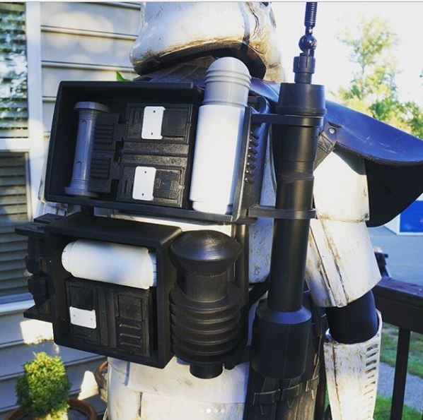
I based my build off of Paul original build thread. This is one of the most comfortable packs you will ever wear.Not many folks, if any have completed that armour build yet. I believe Jim Tripon is offering his version of the armour for sale and a few are building as we speak. The pack itself is a fantastic piece and one of the only modern SW props that still uses all real world, found objects to build it. So far we have identified nearly all the parts of the pack except for a couple of pieces that we are still working on such as the weather shroud and the antenna tip.
The parts of the pack to date include the RAF quick release clip, M75 Swedish back pack frame, LC1/LC2 alice pack, woodland camouflage padded shoulder straps, metal slider buckles from Ebay, polypropylene webbing, cotton canvas webbing, Norwegian grenade case, Avanti Precision X 12ft float rod, surgical tubing, antenna tip and 25mm cam lock buckles.
This can all be listed with vendors in the thread I will post. Some of the items are now very hard to find such as the fishing rod which is now obsolete (I have researched alternative rods that may serve as a good fill in until the original can be sourced on the secondary market) . The RAF clips I have a stash of and if any one wants any for a build I can supply them. The ammo box is becoming increasingly difficult to acquire and prices have soared.
Various techniques have been used to colour/dye and weather the pack and we have done our best to find ways to best mimic what was seen in various displays and on screen etc.
It is a thing of beauty once built and really has a presence about it. Weighing in at at somewhere between 6-7kg when complete it is a beast to wear on long troops as well.
Sent from my SM-G930P using Tapatalk
-
 2
2
-
-
I am currently constructing a Rogue One Sandtrooper Kyber Crystal Backpack for someone and have been taking pictures along the way.
The intent of this thread is to show you where you can get the materials from and how to build this pack. As of today, I have built 5 of these.
The reference photos can be found in another section of this Forum.
The best place to start is with the pack frame:
FRAME:
You can use 2 different styles of frames for the backpack. The easiest one to locate is the Swedish LK 35. I usually can find these on Ebay.
This is one I found on Ebay using the description "Swedish LK 35 Backpack".
Front View:

Back View:

Most likely you will only be able to find these in used condition with dings and scratches. Sometimes you can get lucky and find on that had not been used.
The first thing you want to do is remove the pack and shoulder straps from the pack.
Frame Front View:

Frame Back View:

Once everything is removed, lightly sand the frame to remove any rust or corrosion. Then add a prime coat and at least 2 coats of flat or satin black spray paint.

The Frame is now ready. Next will be the Grenade Box.
-
1
-
1
-
-
Here are some of the reference photos I have used that you did not post above.


One of my packs:


-
1
-
-
I will send you pictures that I haveJust as long as someone can provide me with a clear picture of the Kyber pack for the CRL I'm a happy trooper.
Sent from my SM-G930P using Tapatalk
-
1
-
-
Revised pictures have been submitted. I am pretty sure it's under final review. But Dutchy or lovemonkey can let you know for sureIs there any news from the CRL?
Sent from my SM-G930P using Tapatalk
-
I do not think you are going to find a picture with someone wearing R1 armor with one of the packs. Your best bet will be to either just show the TD without the pack or photo shop it in. You could always add a disclaimer below the picture stating that a more appropriate picture will be added once you have a model.
-
Sure thing. I am actually starting today.
-
I have good pics and am just starting to build another one right now. There are some threads on FISD we might be able to pull over from FISD.
Sent from my SM-G930P using Tapatalk -
I have pack pictures if you need them.
Sent from my SM-G930P using Tapatalk -
Anyone have a good setup for the Sonic Radio?
-
That is awesomeThis one is really nice, especially as there are cadets from the GA in it!
Sent from my SM-G930P using Tapatalk
-
9 minutes ago, Brokk said:
This trooper here is currently deployed with this exact pack. Sean, your work is top notch. I'm trying to get better pics taken, like action shots with my brother who is a photographer. What drew me to this pack is how it reminded me of the old radio packs the troops used in WW2; the grunt look which in my opinion what the trooper is all about. As well as my love for Rogue One.
Hit Sean up if you need a pack guys
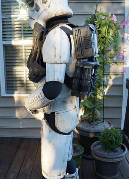
Thank you for posting the cool picks and the great comments.
-
Thank youAmazing work as always Shawn!
Sent from my SM-G930P using Tapatalk
-
Thank youAmazing work as always Shawn!
Sent from my SM-G930P using Tapatalk
-
No problemWow! Great job, Shawn! Thanks for sharing your process!
Sent from my SM-G930P using Tapatalk
-
On 2/13/2017 at 1:00 AM, Daetrin said:
IIRC the shins are supposed to be grey? IIRC you were re-painting them - were they completed?
Shin armor has been repainted. Pictures are below.:
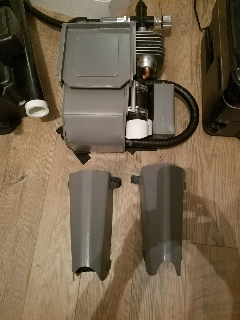
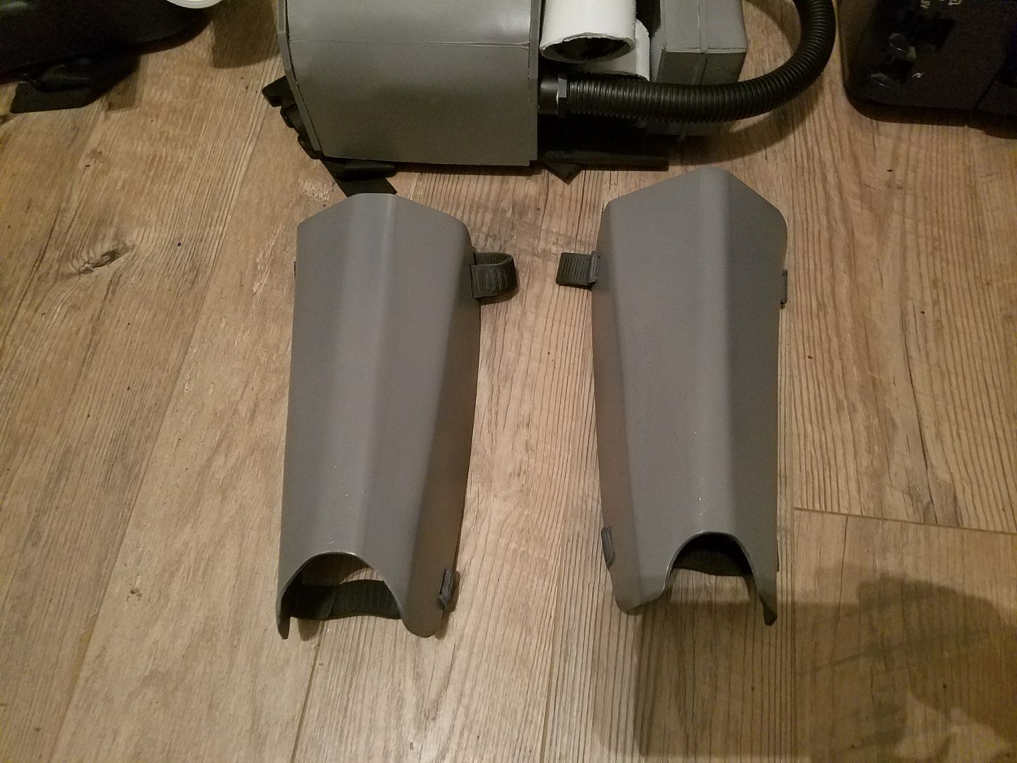
I will also update this in Spec Ops.
-
1
-
-
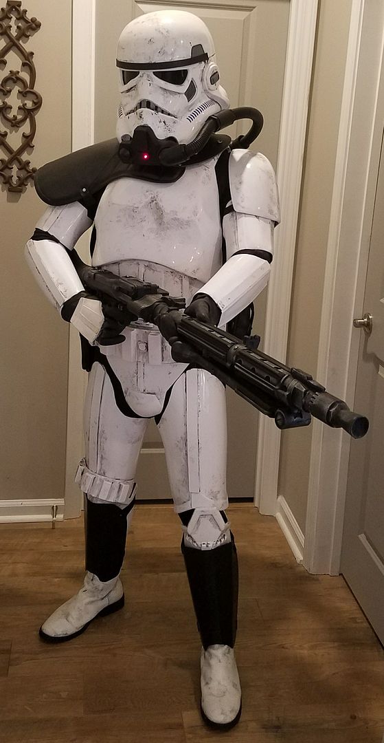
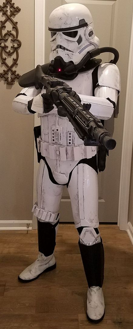
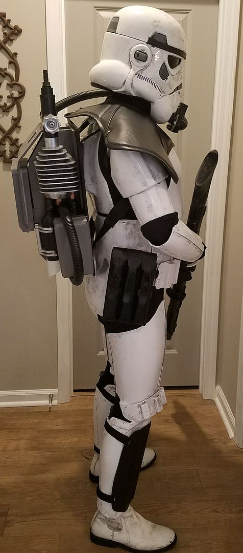
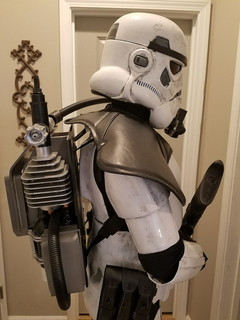
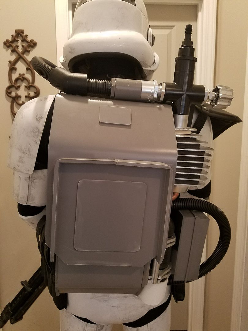
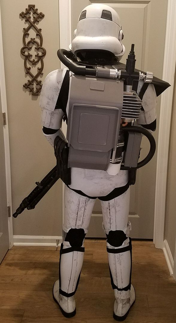
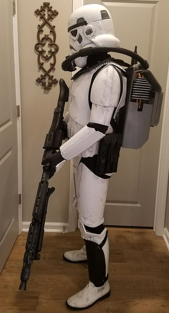
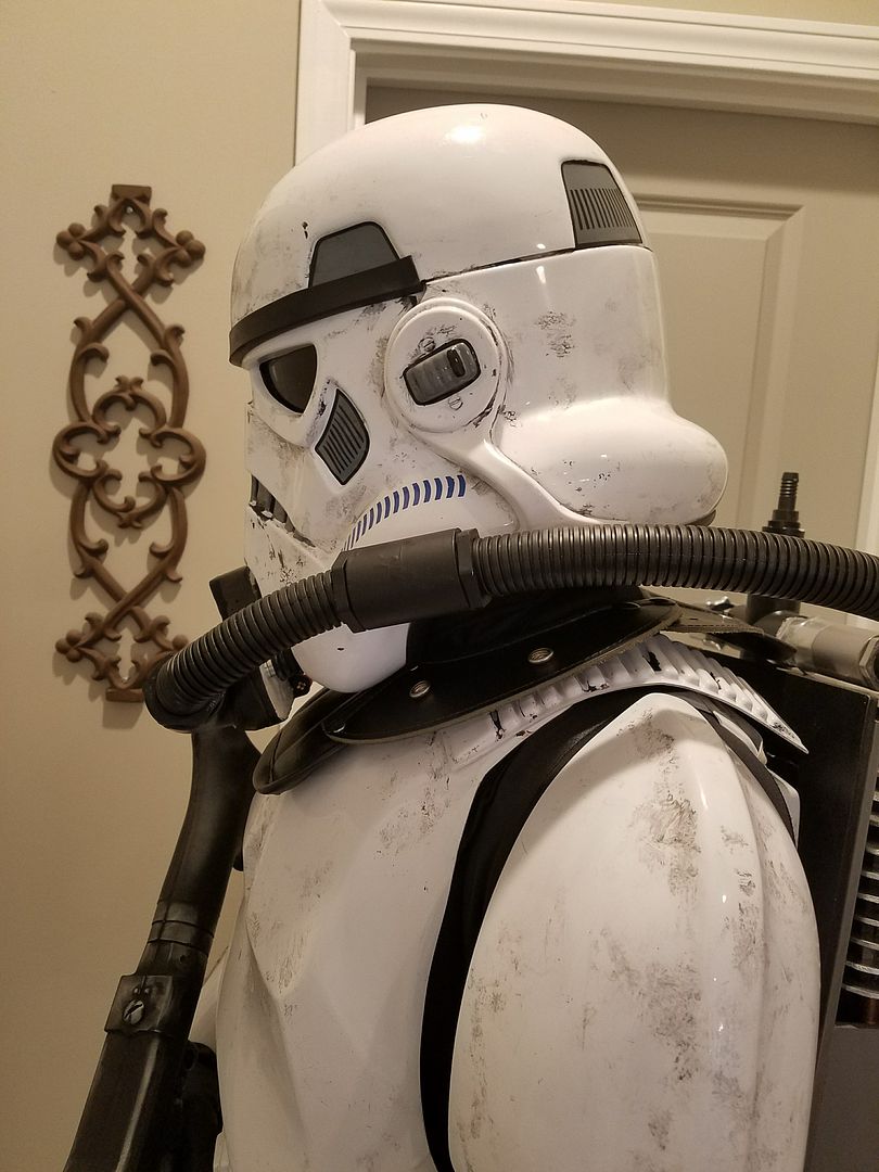
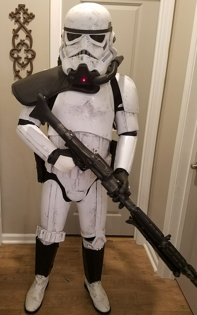
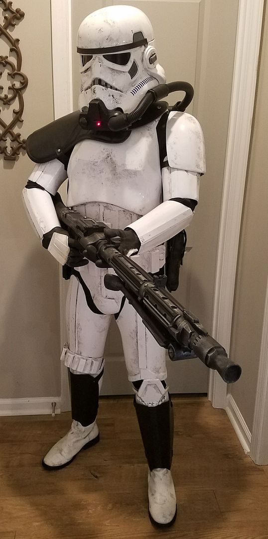
Finished with this build. Will post more pics and details of the build, later. But below are the photos.
-
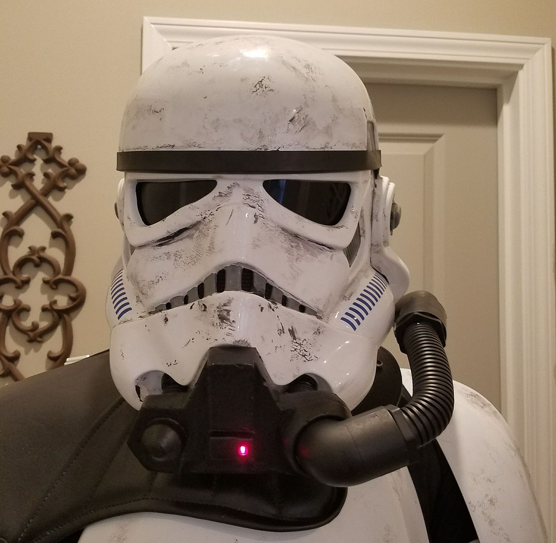
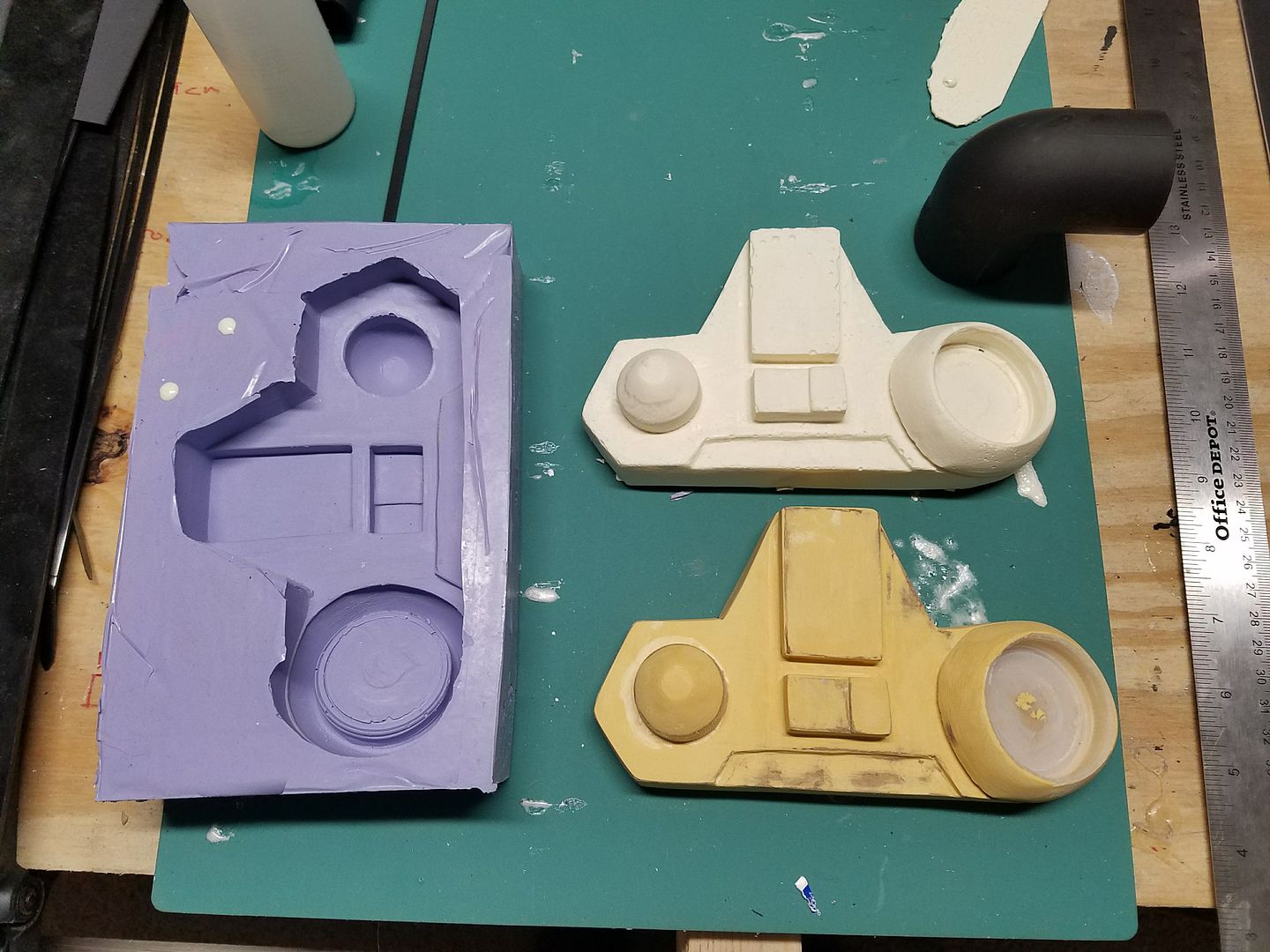
THIS WAS THE OLD WAY I DID IT. NOW I 3D PRINT THIS PART. IT IS MUCH LIGHTER AND MORE ACCURATE.
The respirator model and mold are complete. This is a picture of the first resin one. Now all I have to do is add the red LED Light, paint black and install the magnets to hold onto the helmet.
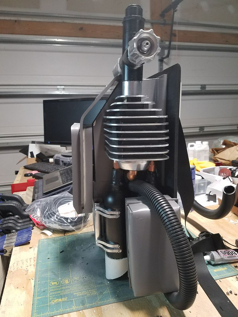
I am now at the point where I can put the final touches on this entire package (pack, shin armor, respirator system).
-
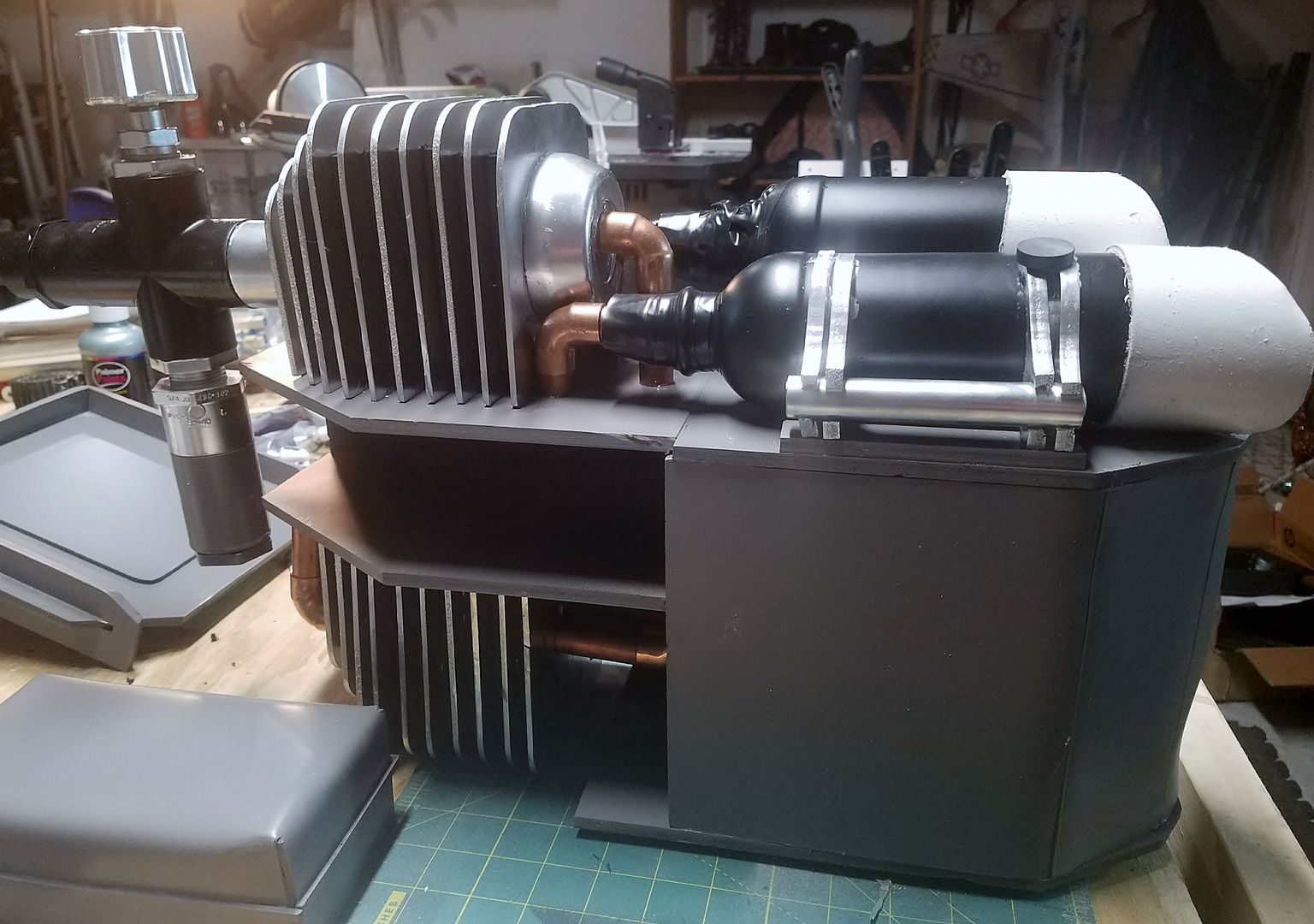
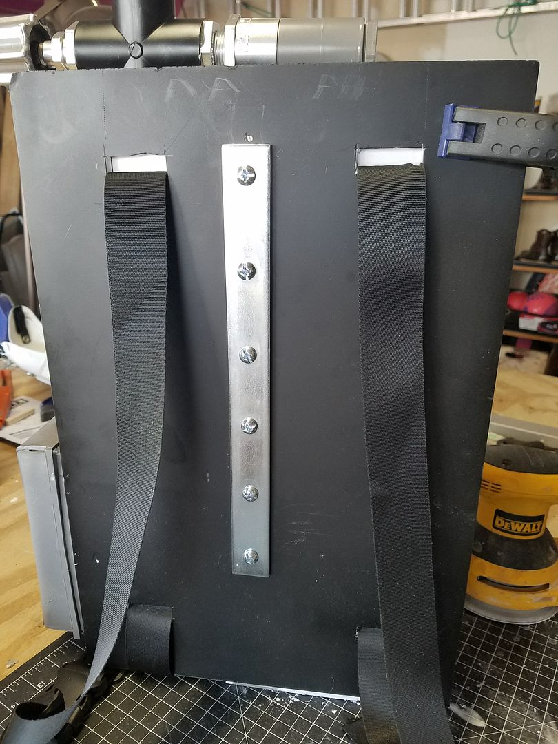
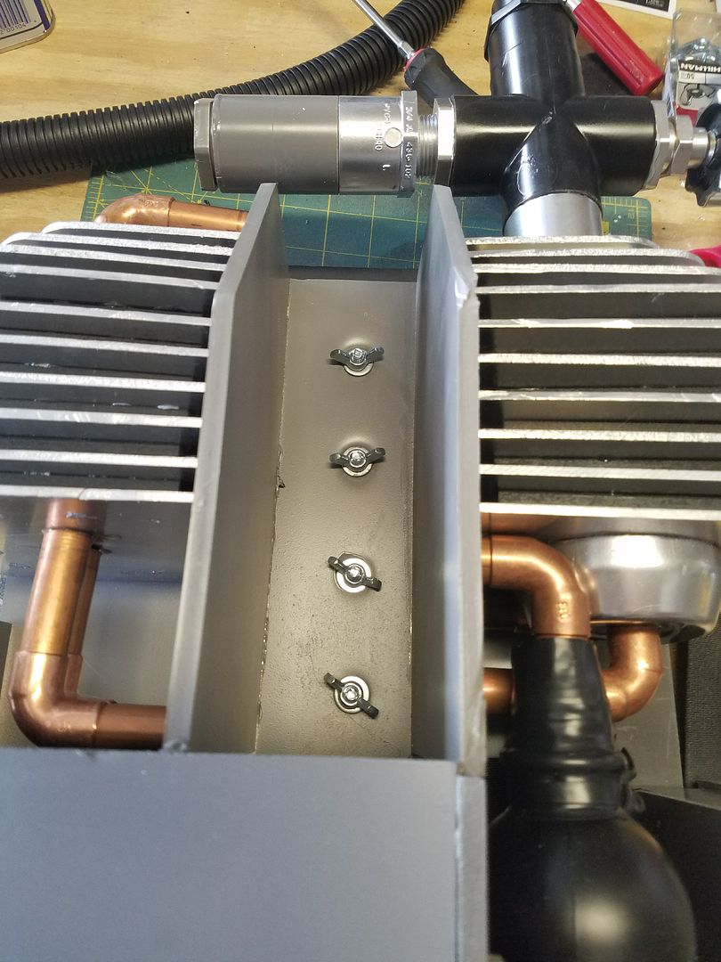
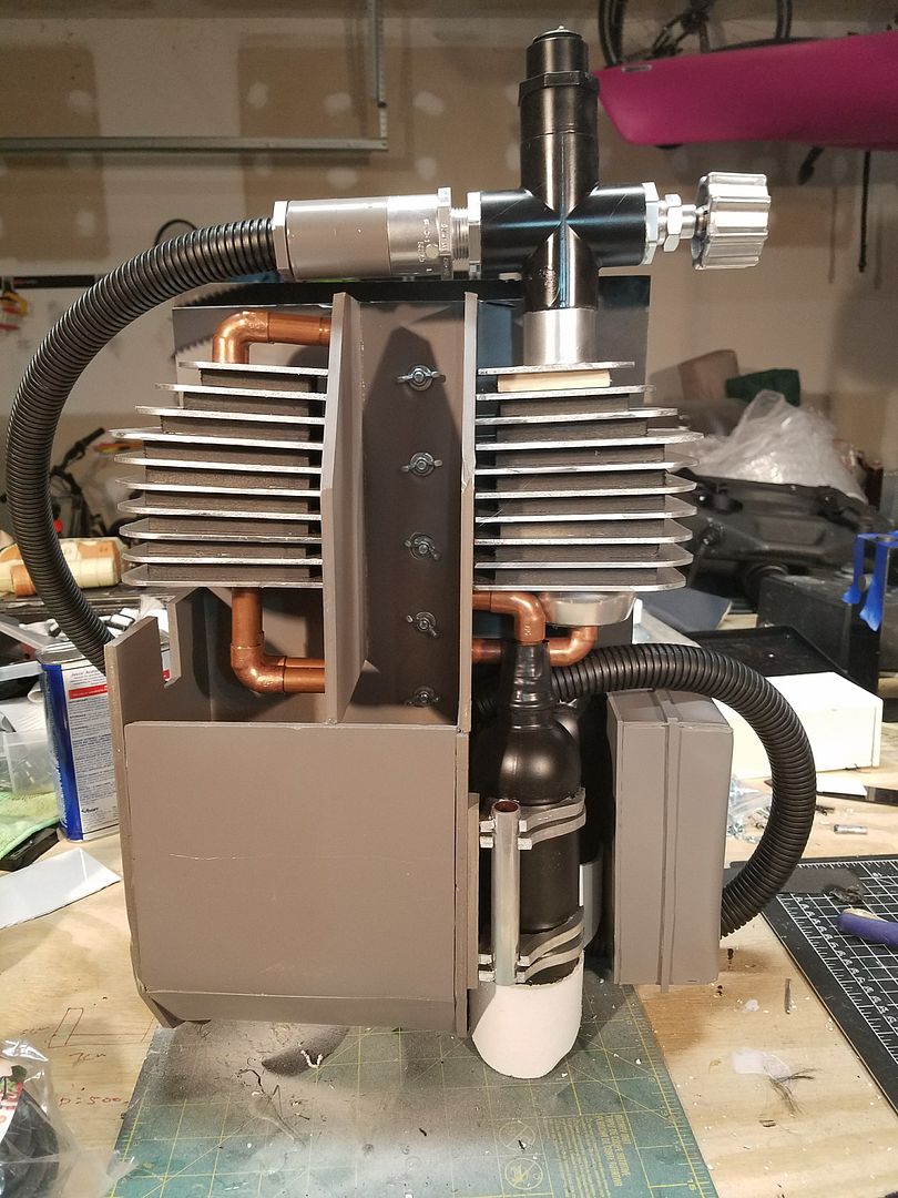
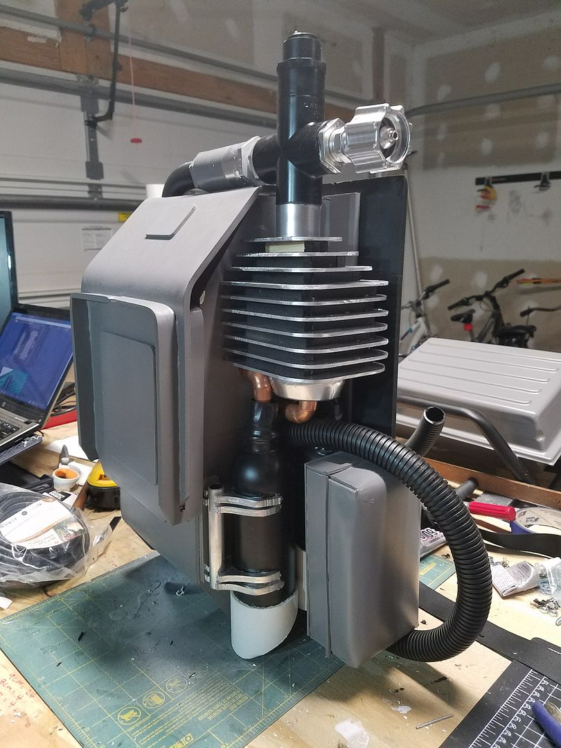
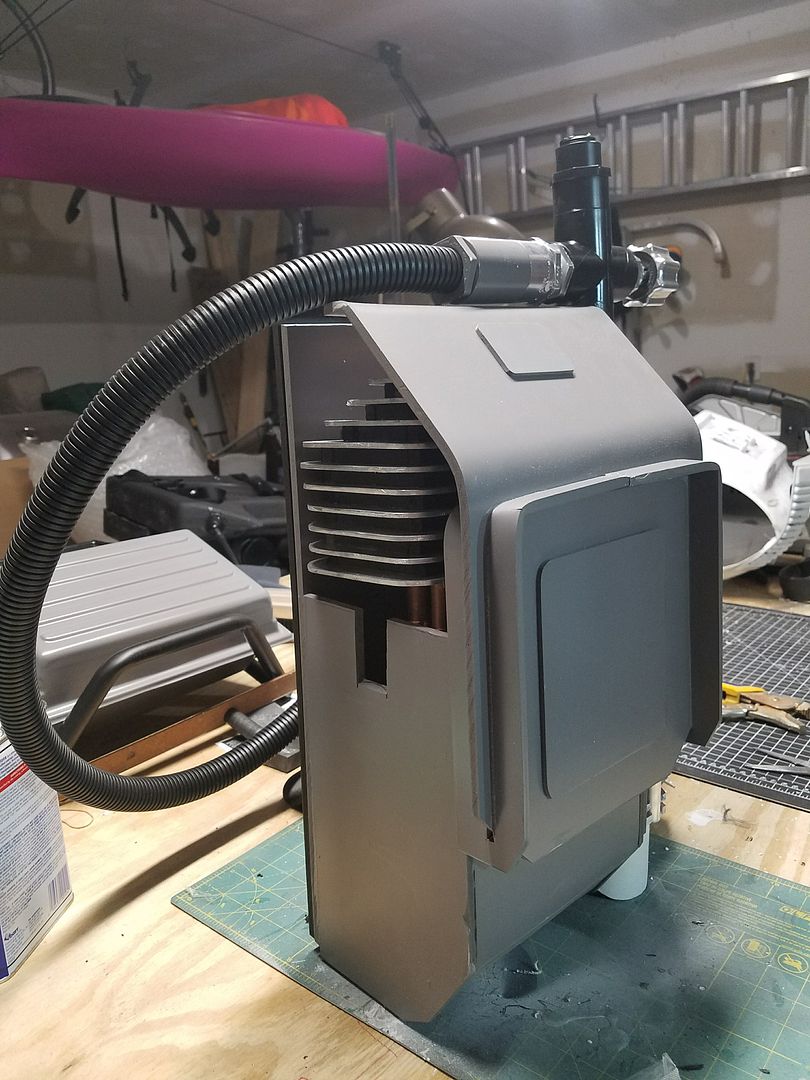
Getting very close. I have added the tubing, reinforced the back, added the shoulder straps, completed the copper work, attached the exhaust port, and many other items.
I still have to correct the imperfections, weather the pack, add the vertical details on the fins, connect the tubing to the helmet and add the respirator.
Below are some more pictures of the progress:
-
CONSTRUCTION SECTION 3:
In order to keep each post to a reasonable length, I will be breaking the remaining portions of the builds into additional sections.
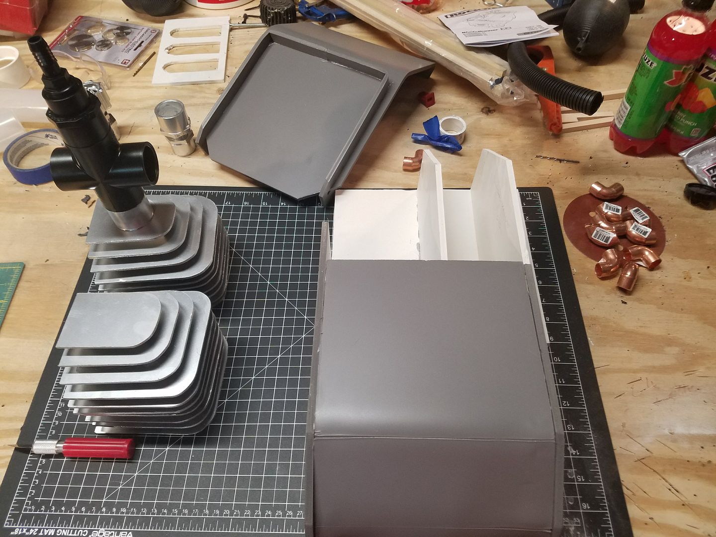
Below is my latest progress. I know I am currently jumping around a little bit, however, I only have time at night to work on the build, so I have to work on different items at the same time. Once I am 100% complete, I will go back and make final revisions.
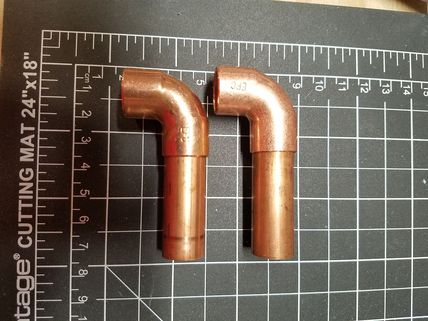
I am currently working on the copper piping on both the left side and right side of the pack.
For this I am using 2 cm diameter copper pipe and elbows. I cut the pipe to 5.5 cm in length. I cut 6 pieces and used 4 elbows for the left side.
This is for the top section:
Bottom section:
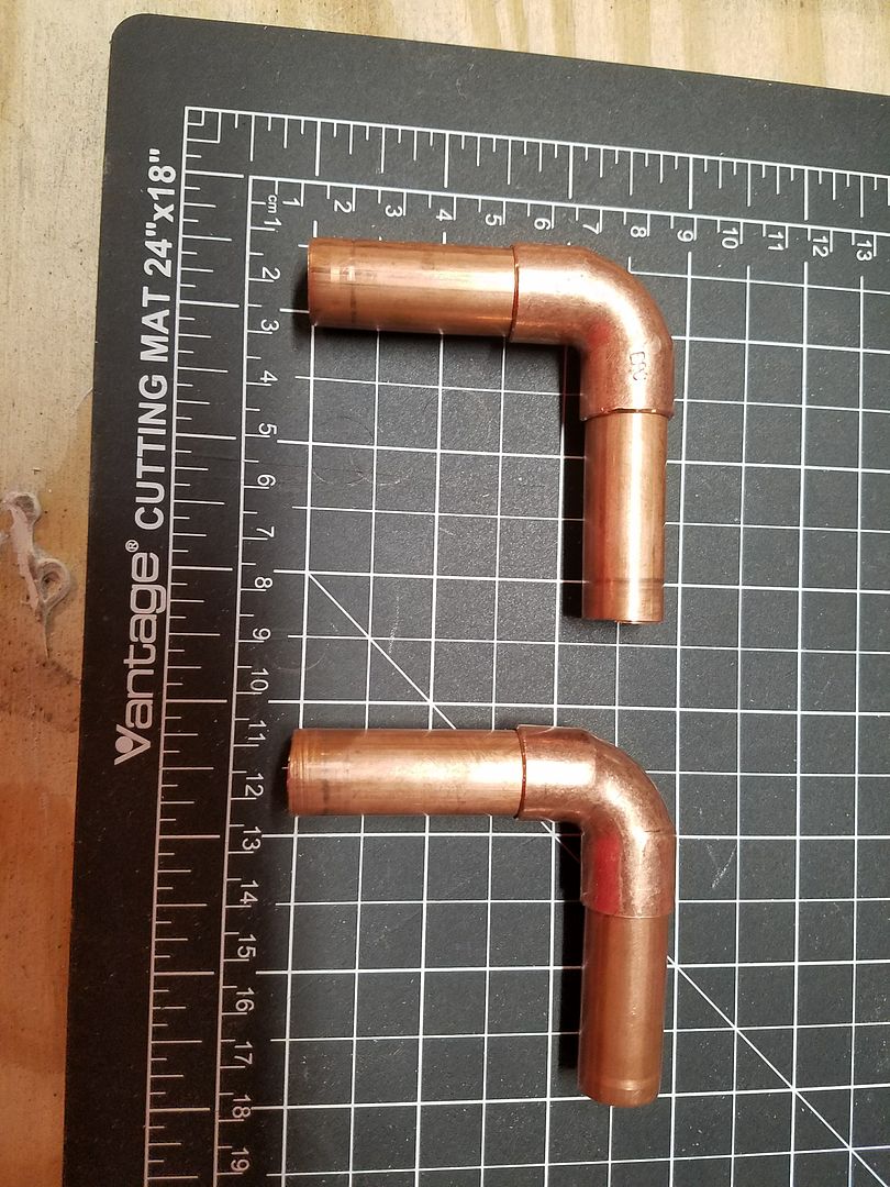
Glued the 4 pieces onto the Fins and Pack.
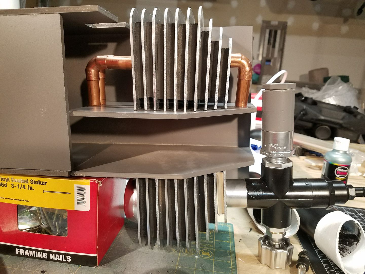
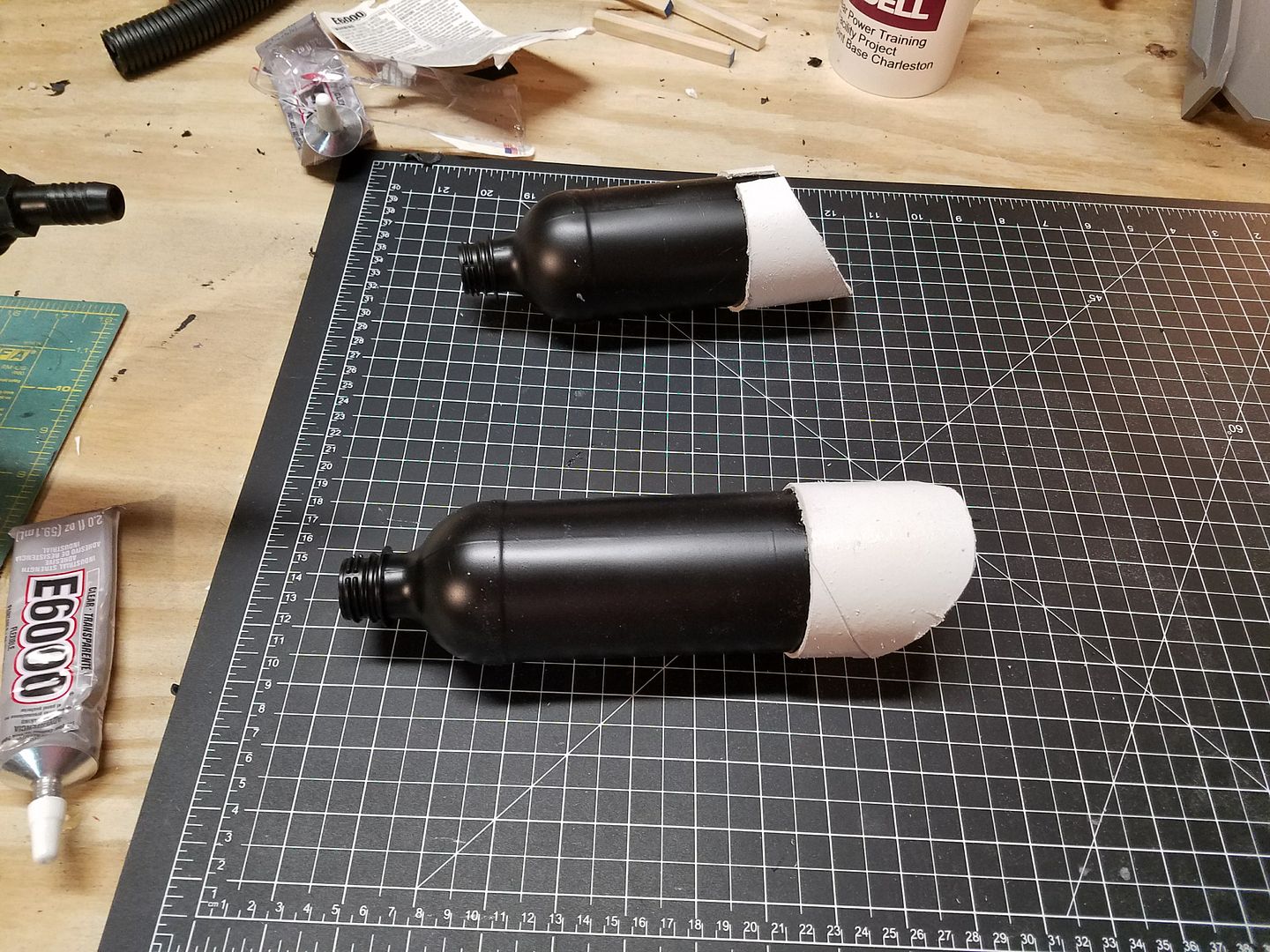
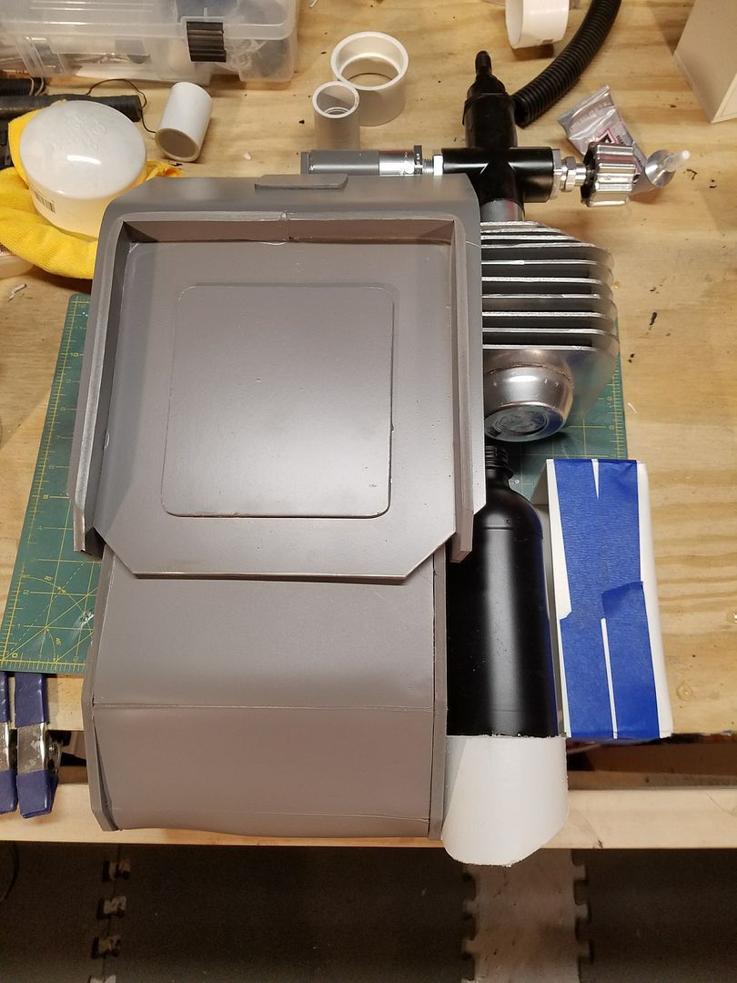
For the 2 exhaust ports (bottom right of the pack), I started with 2 plastic drink bottles:
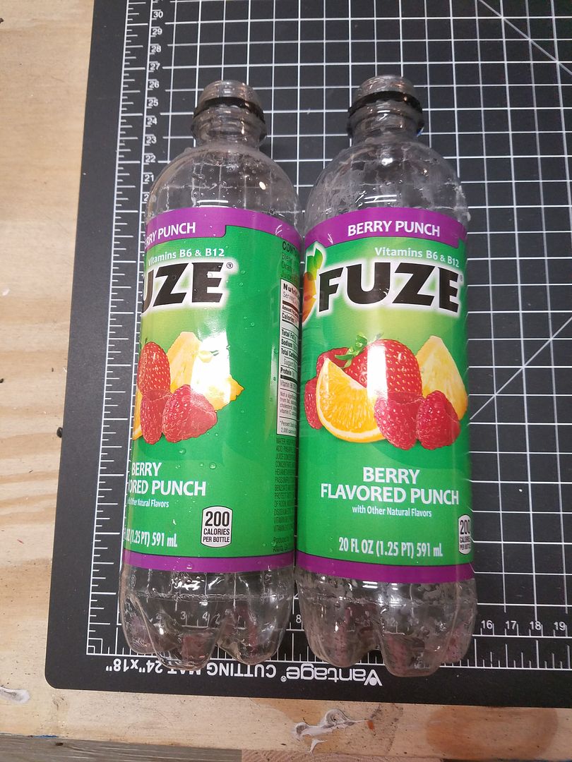
I then removed the labeling and cleaned them:
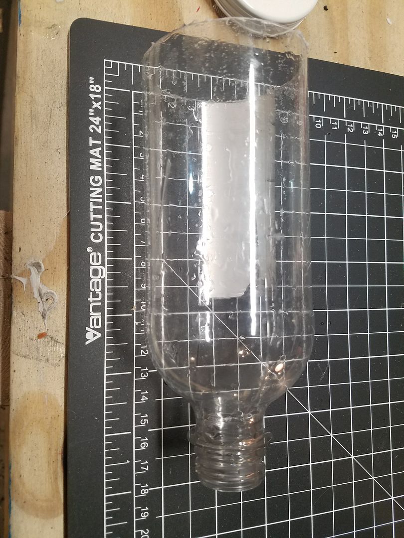
I then cut off the bottoms of the bottles and painted them flat black.
While I was waiting for them to dry, I worked on the angled portion of the exhaust ports. I decided to use a cardboard tube container. It is very thick and durable. I cut the pieces at a 45 degree angle. In order for them to fit properly over the bottle, I had to cut a slit in the back..
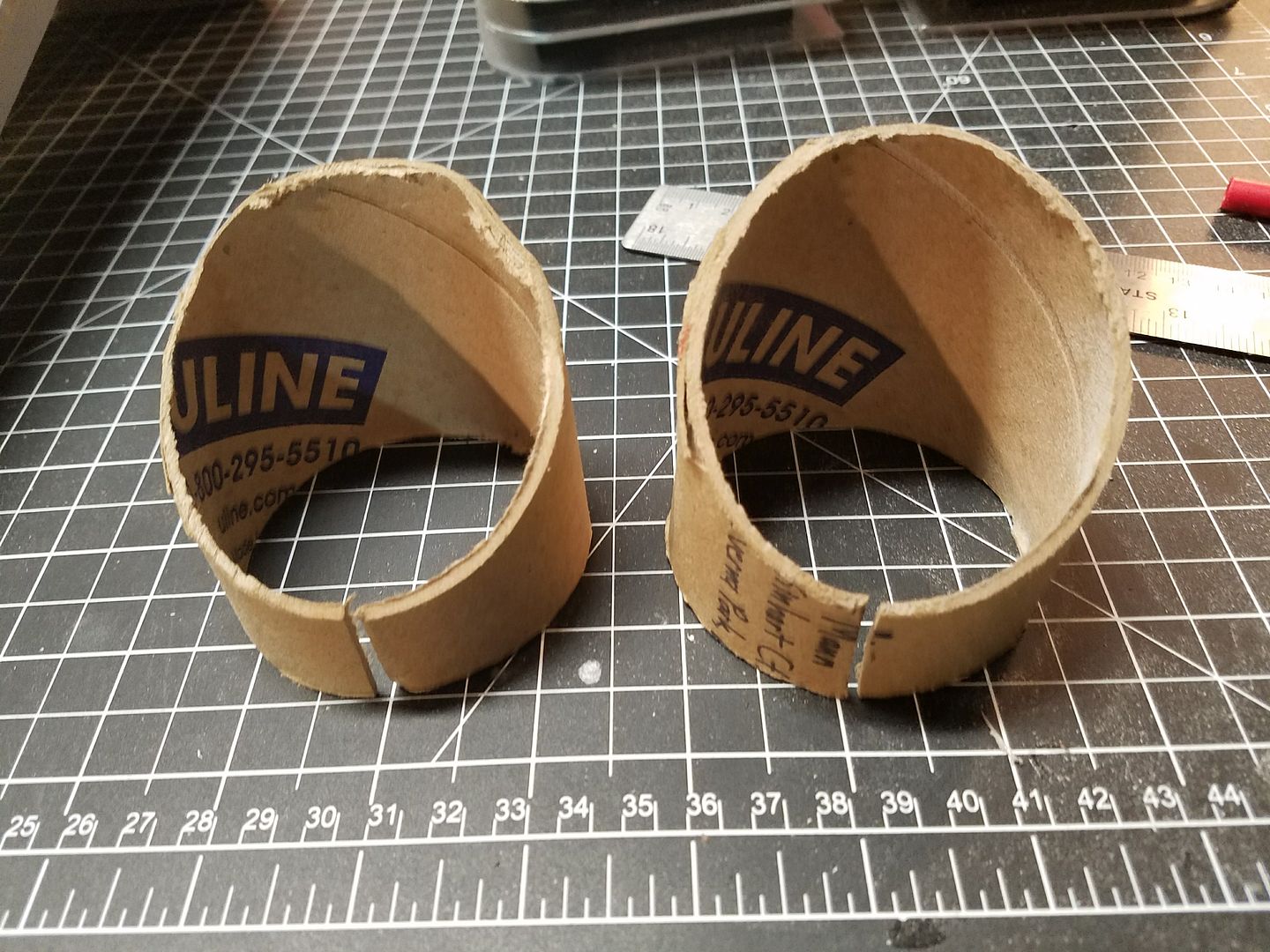
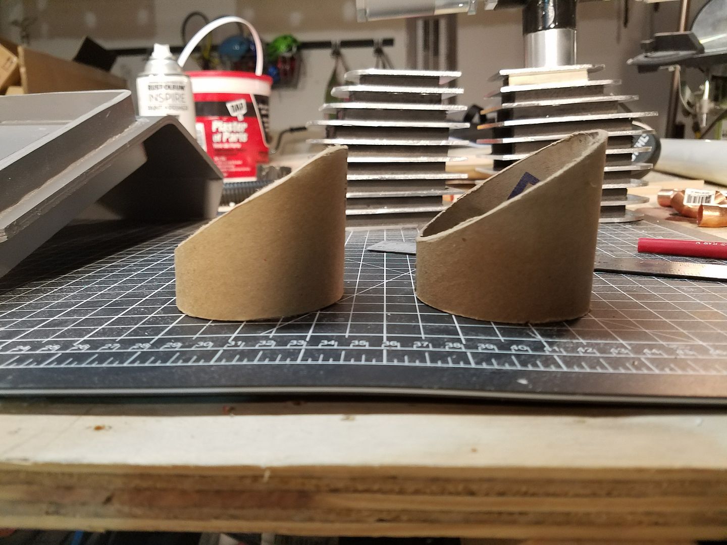
I then added many coats of white primer and gloss paint to these pieces. Once dry, I glued them to the bottles. You will notice that one of the bottles, I cut shorter to match the reference pictures.
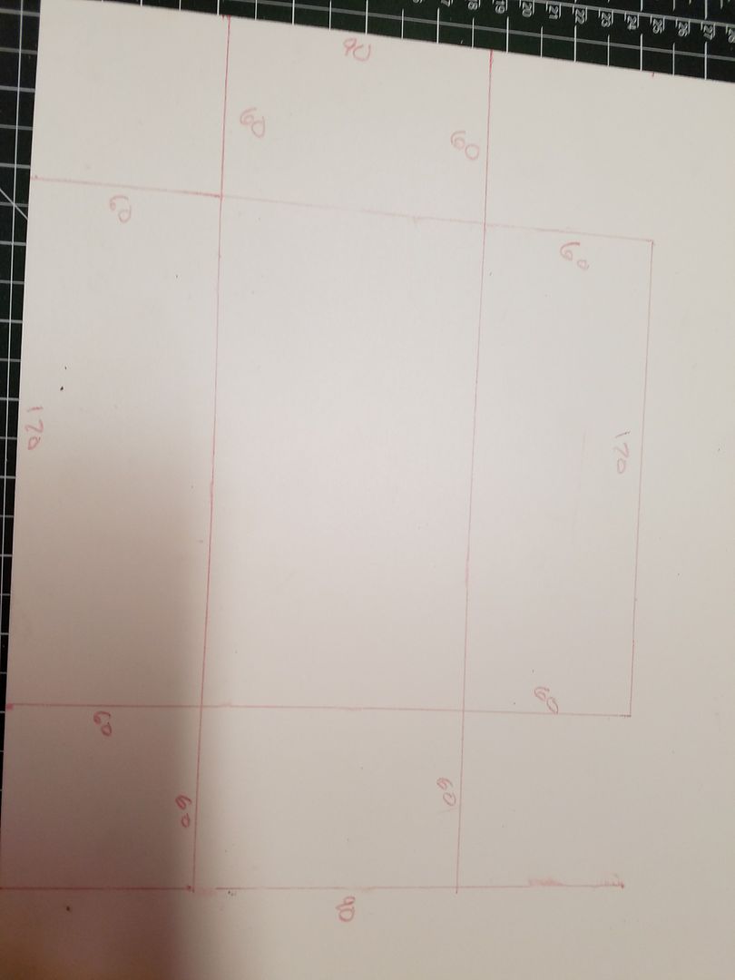
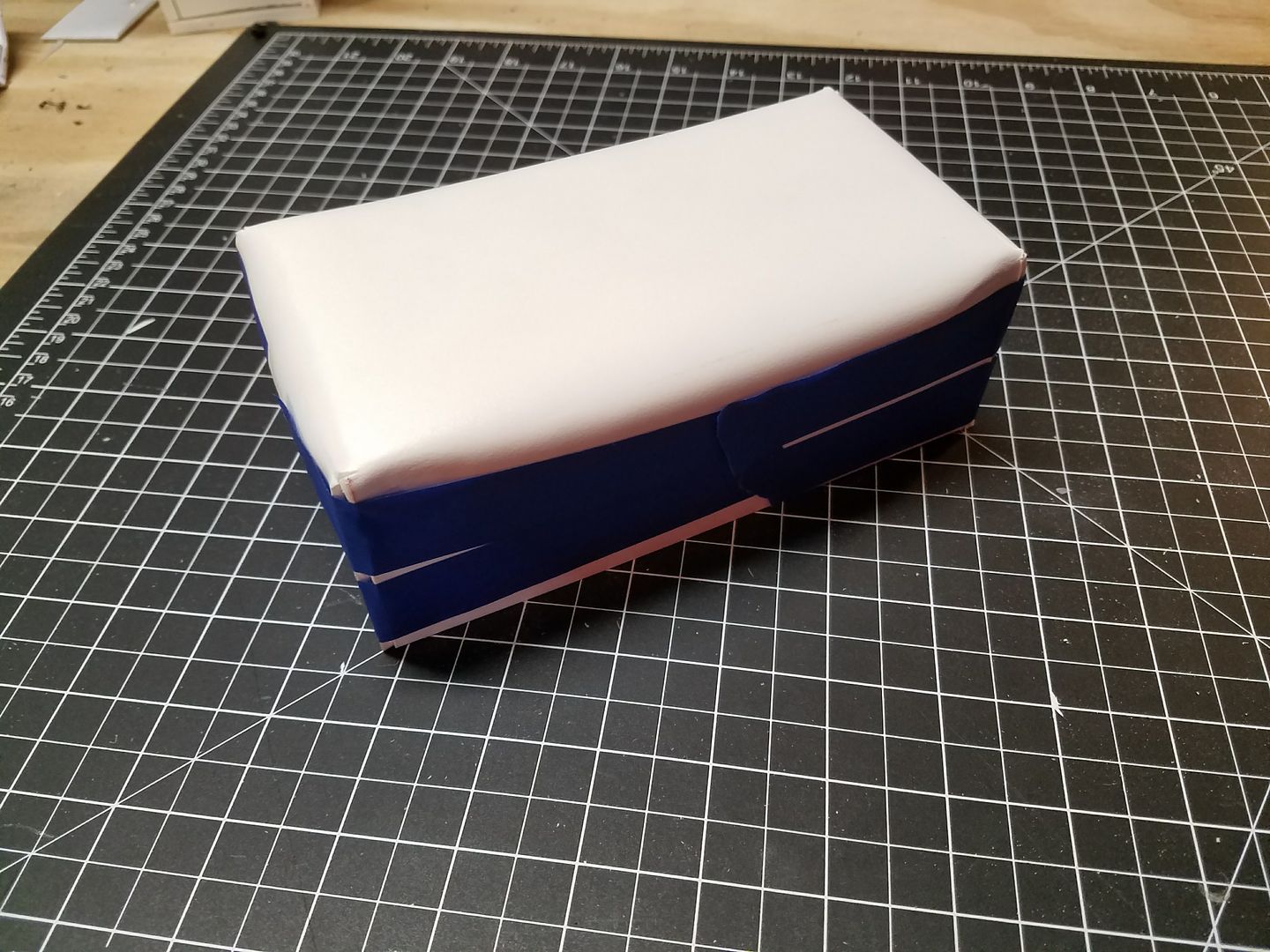
Next I worked on the box that is on the bottom right of the pack, directly adjacent to the exhaust ports.
Below are the photos. I will add the text, later.
-
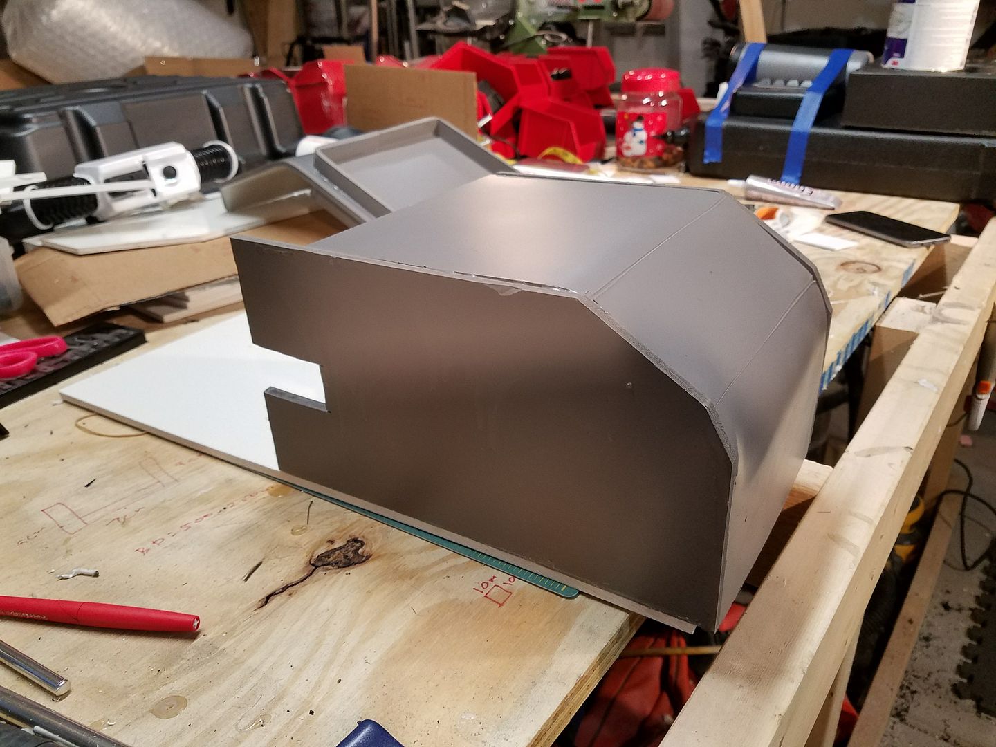
Ok. I have spent the last couple of days working ******* this thing.
First thing I noticed was that I put the side panels on backwards. The part with the notch needs to be on the left side of the pack. Below is the corrected version.
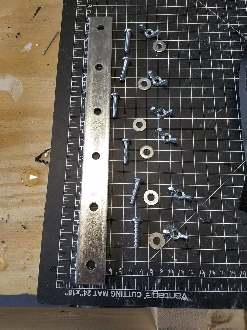
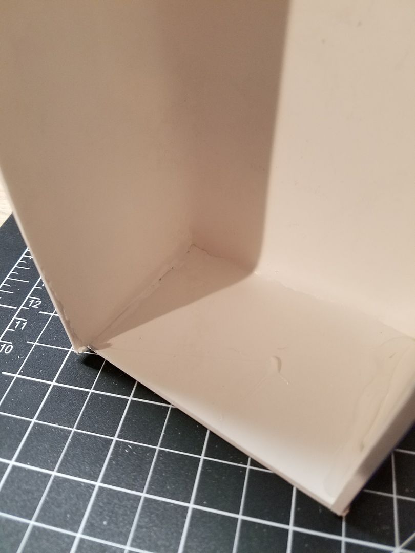
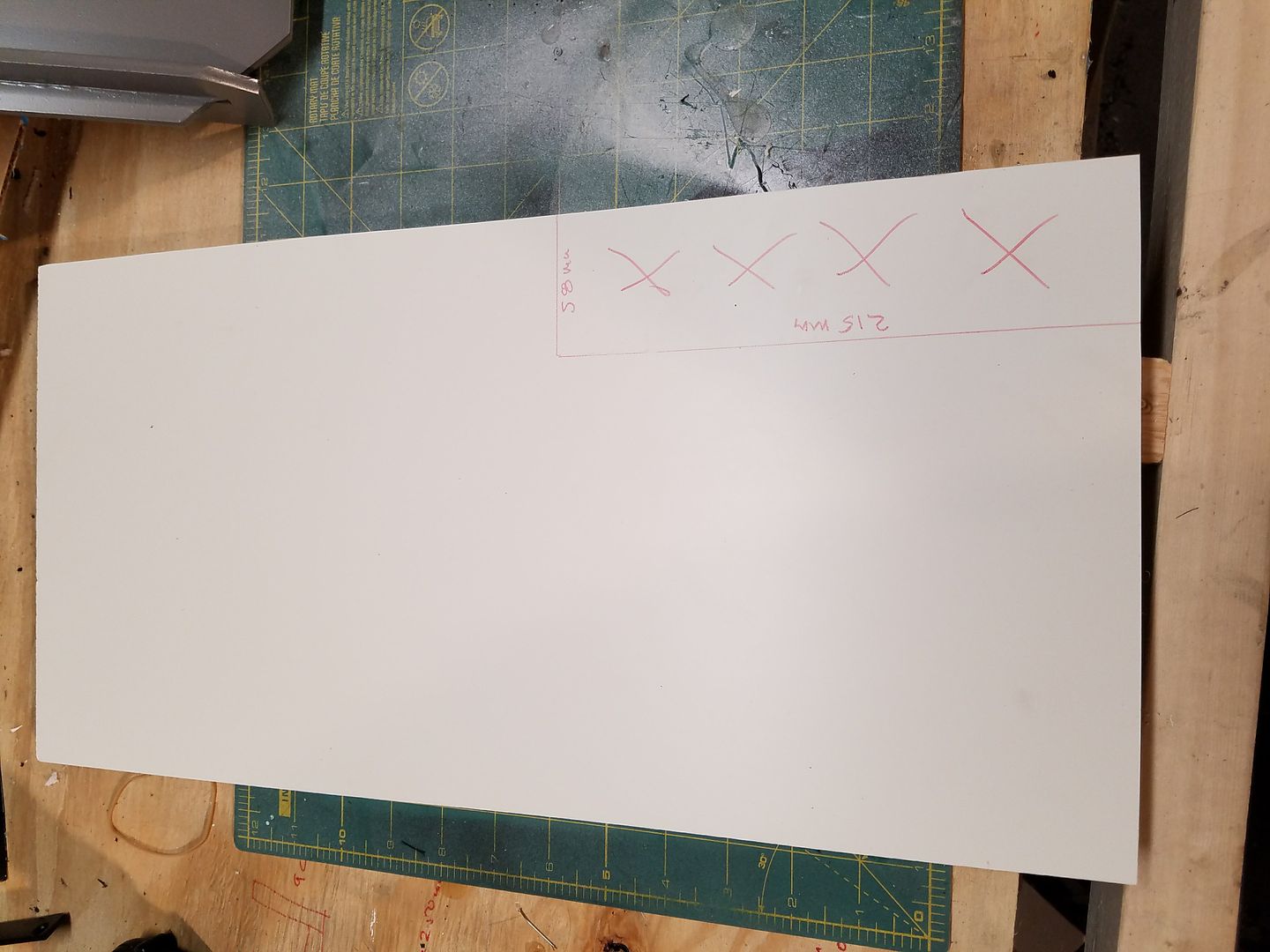
After I corrected that mistake (this happens when working on a prototype for future builds). I cut out the back plate 500 mm x 250 mm.
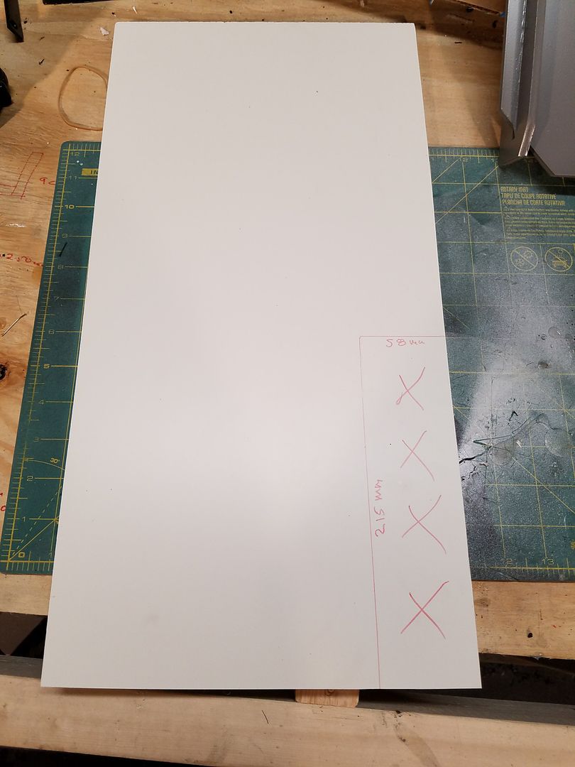
I then cut out the 215 mm x 58 mm section at the bottom right.
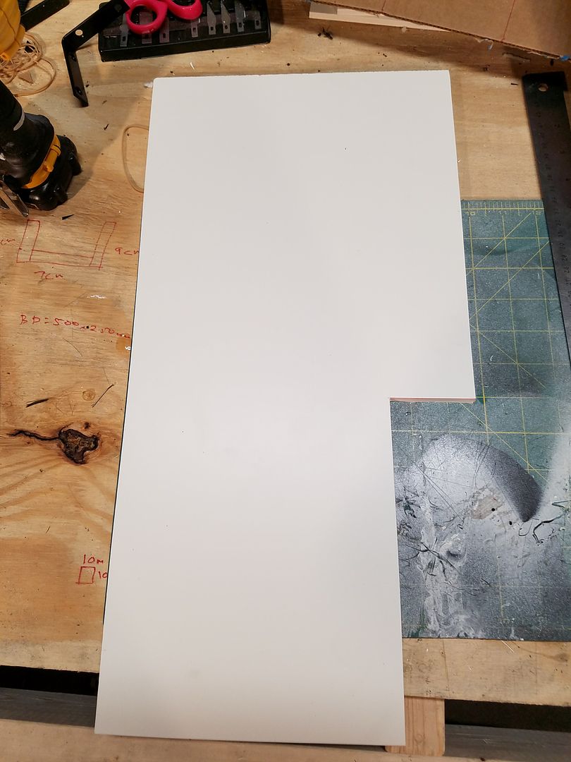
Then glued the finished portions to the back plate.
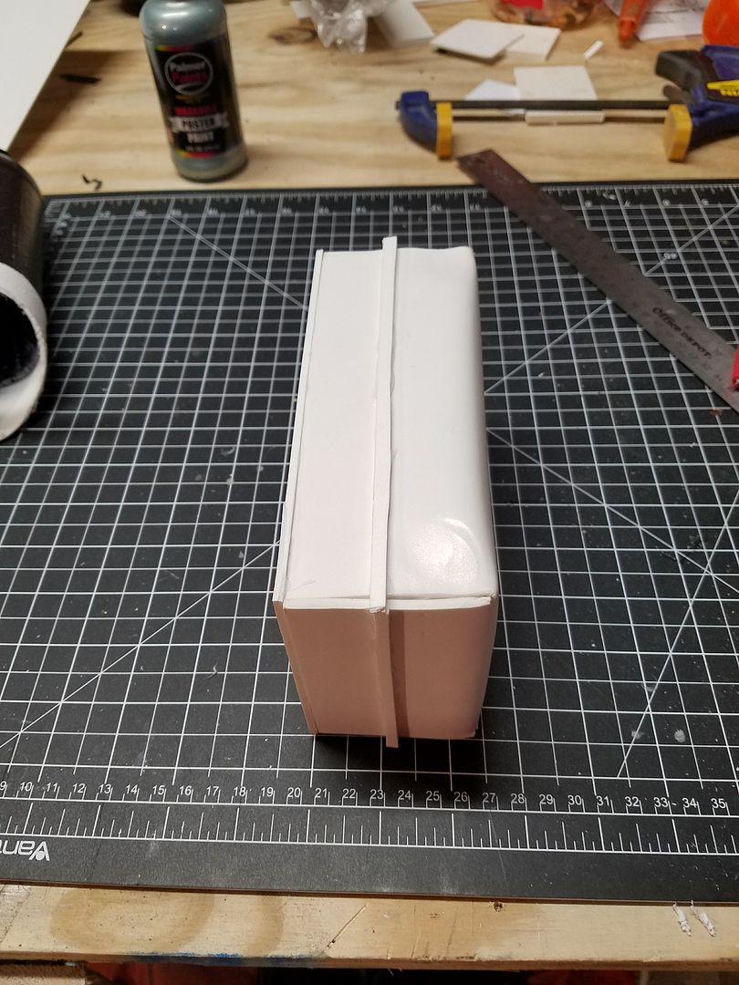
I then glued the previously cut top angles to the back plate. (only 1 shown below)
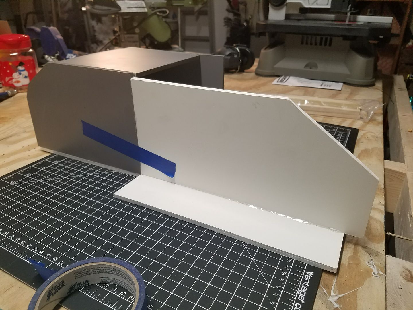
When I test fit the top plate over these, it appeared they were too long. Therefore I had to remove them and cut them down.
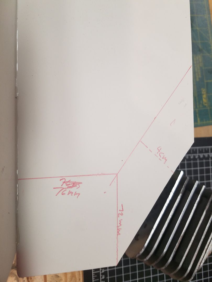
At the same time, I shortened the back plate by 75 mm and glued the two angle pieces back on. You will notice the fins and some other pieces are on the left side of the photo. These will be discussed in another section.
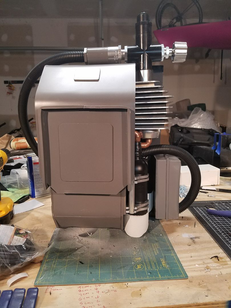
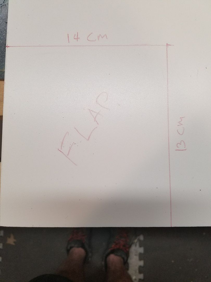
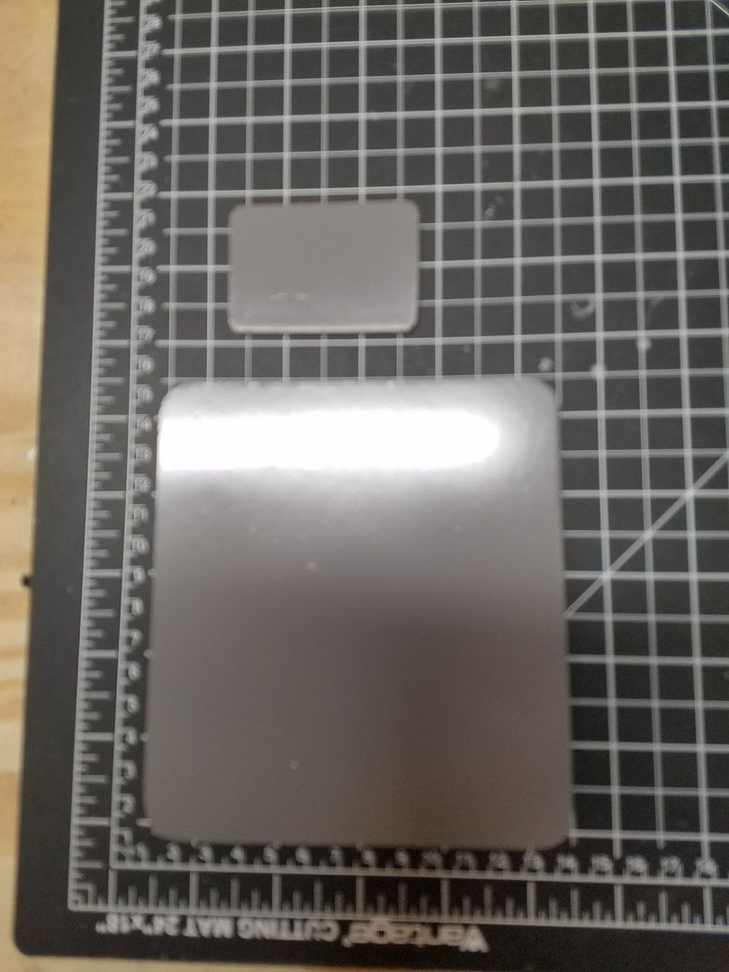
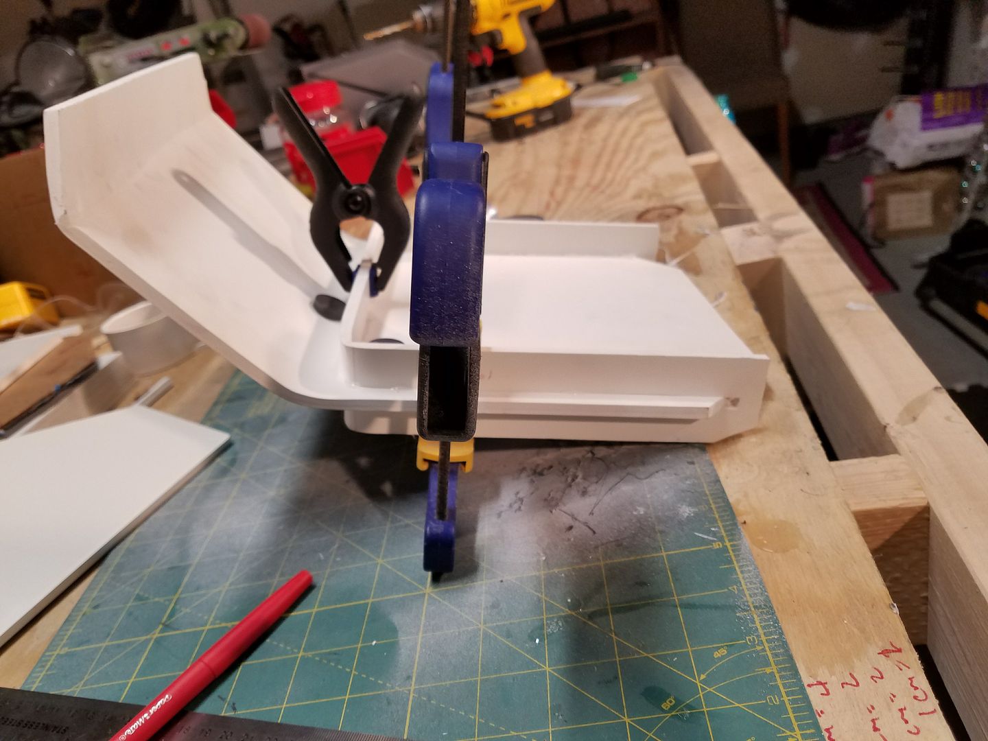
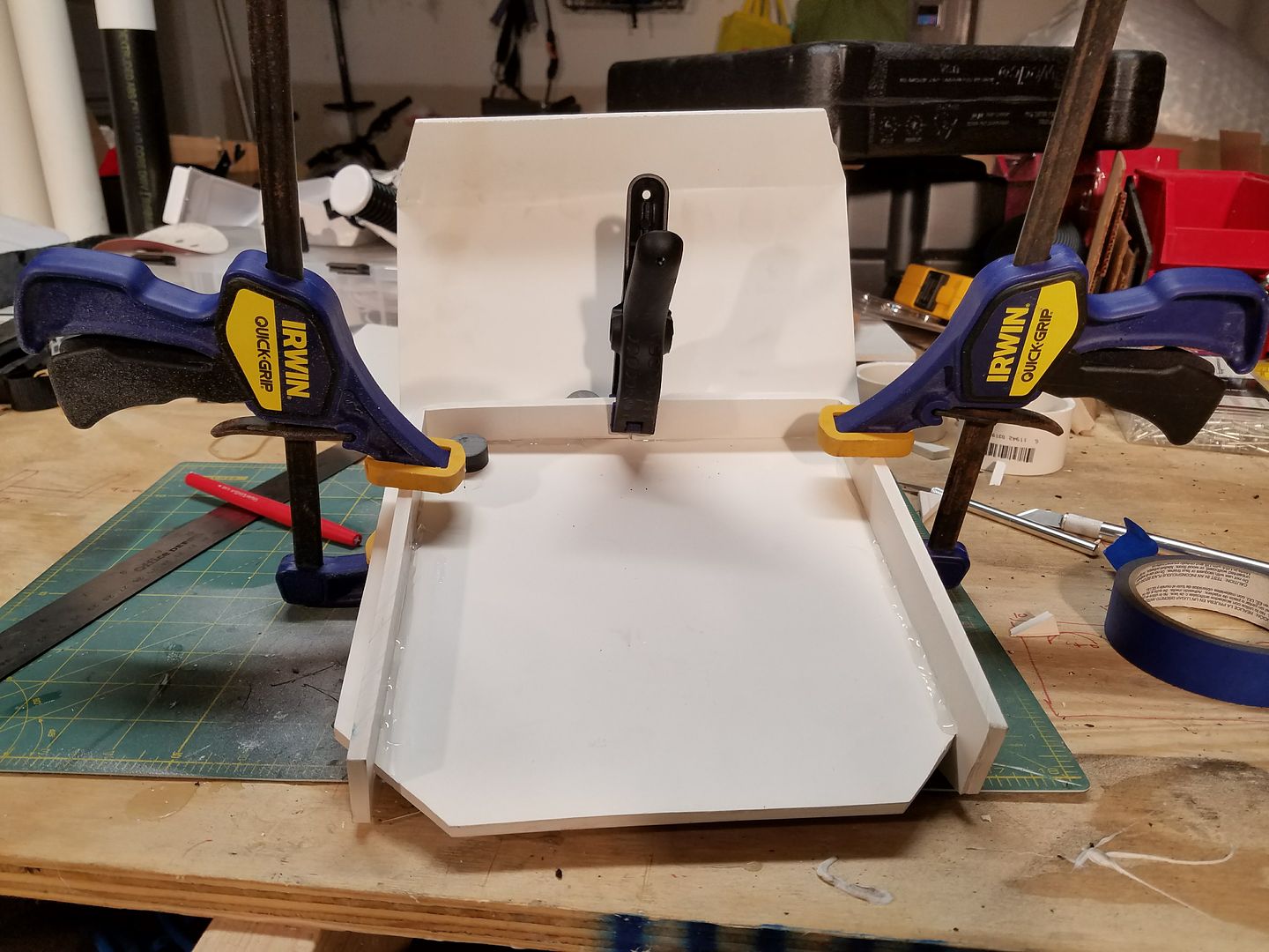
For what I am calling the access hatch on the face plate, I created this out of the 1/8" PVC board and cut out a 14 cm x 13 cm rectangle. I had actually cut out a hole on the face plate at 13cm x 12cm, however, I could not get it to function correctly. So for this prototype I am going to keep the access hatch on top of the plate instead of flush. I will see if I can make an operational hatch for Version 3.
For the upper small "Name Plate" on the face plate, I cut a 4 cm x 6 cm rectangle out of the same 1/8 pvc board.
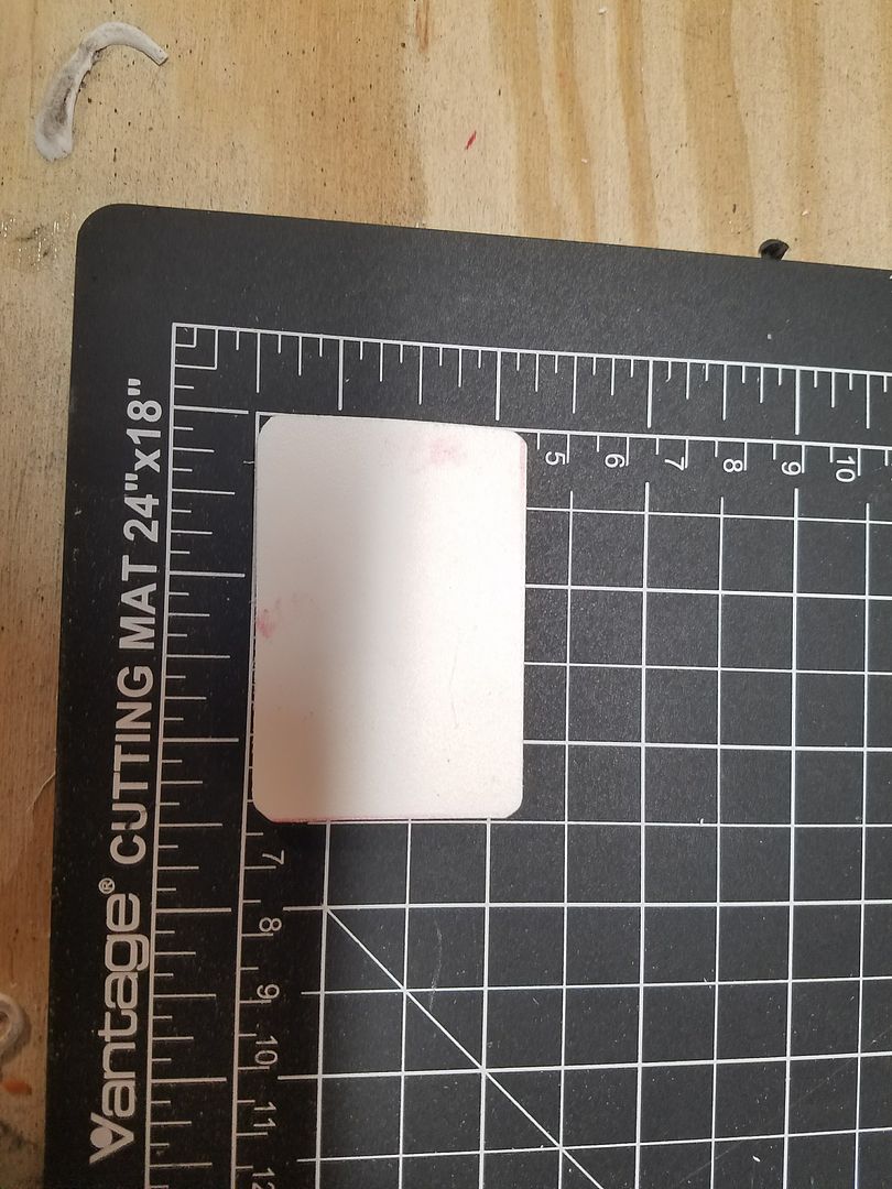
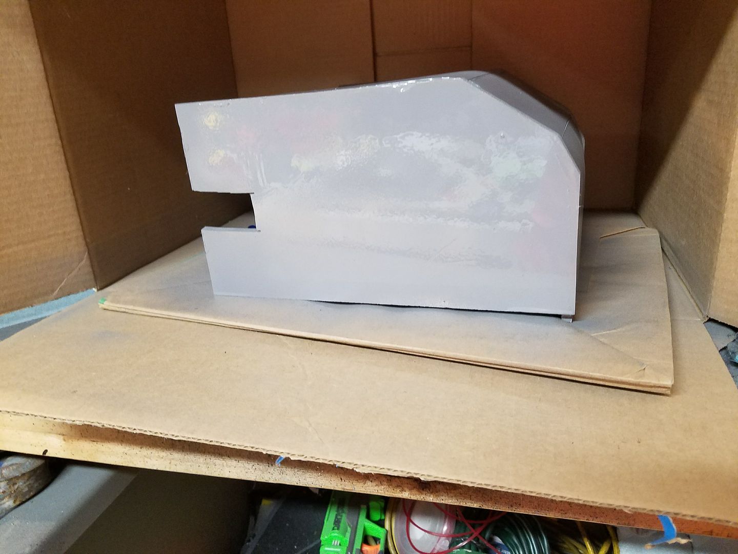
These are the 2 plates after 2 coats of the flat gray spray paint.
Here is a picture with the plates attached.
-
CONSTRUCTION SECTION 2:
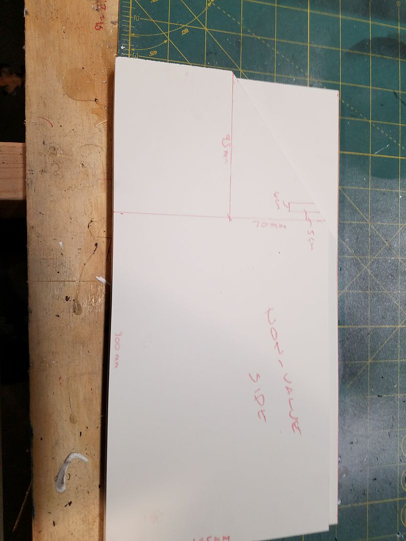
LEFT SIDE FRONT PLATE AND PANELS
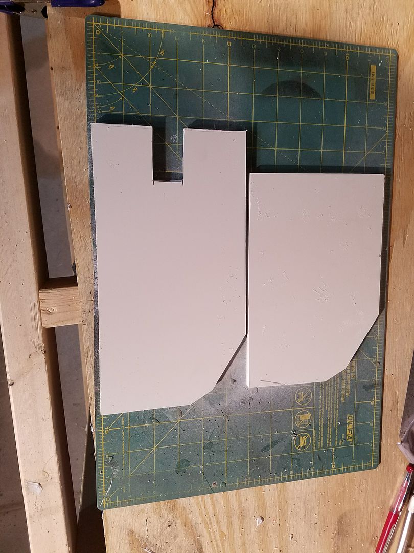
First, I decided to create the left and right bottom of panels. As I continue to do this, I will make it more clear the area I am working on. I am learning this as I go along.
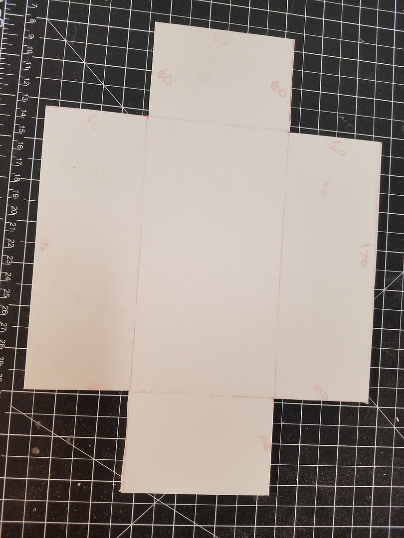
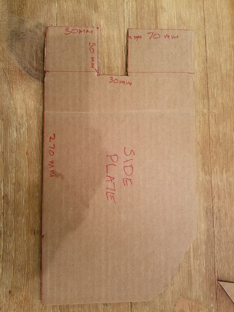
I made templates out of cardboard, so I could do this again and again.
This is left side panel:
This is the right side panel (plate): Before I trimmed it.
I then placed the template on the 1/4" PVC Expanded Plastic Sheet and traced both of them.
At this point, I used the dremel tool to make the cut and the table sander to clean the edges. Below is the final result.
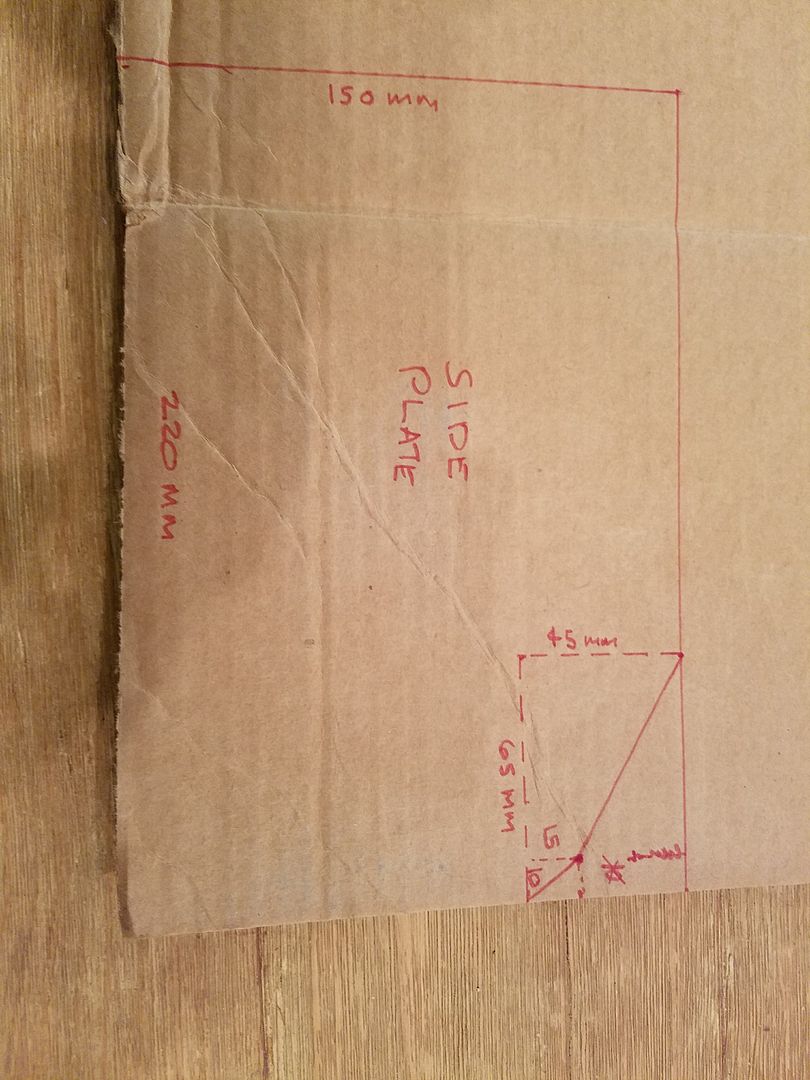
Below is the template I made for the front plate that these 2 side plates attach to. Once you cut this out of the PVC, it has to be bent into shape by heating up the pvc where you need to bend it. Unfortunately, I did not take any pictures of this process.
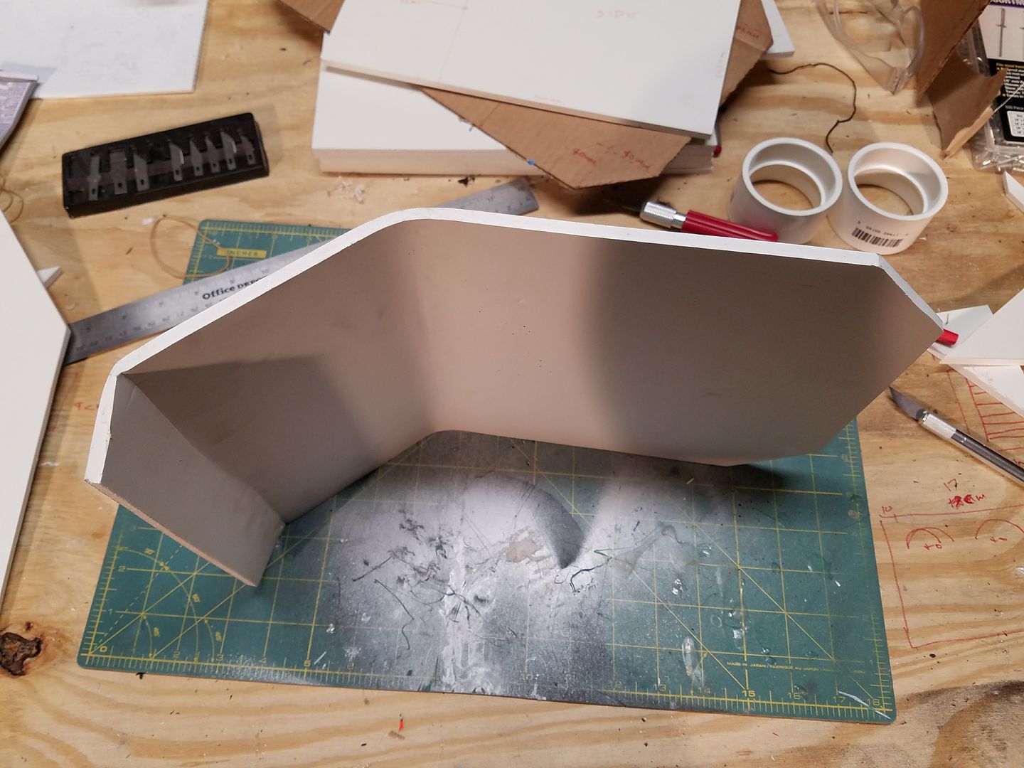
Below was my first attempt at glueing all of the pieces together. However, I glued the side pieces on backwards. Do do not do it this way.
After I painted it, I realized I had put the longer side with the notch on the wrong side. When facting the pack, it needs to be on the left. See pictures below:
Next, I cut the backplate at 500 mm x 250 mm, as a starting point. this will be trimmed as I go along.
I then placed the piece on the back piece and traced out the right section. The piece to the left will need to be removed.
I then glued the 2 pieces togther..
Now that we have got the bottom panel / plates glued together, it is time to work on the upper portion.
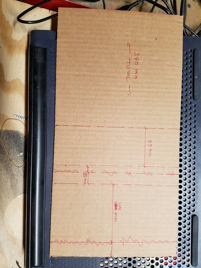
I started with a template created from cardboard.
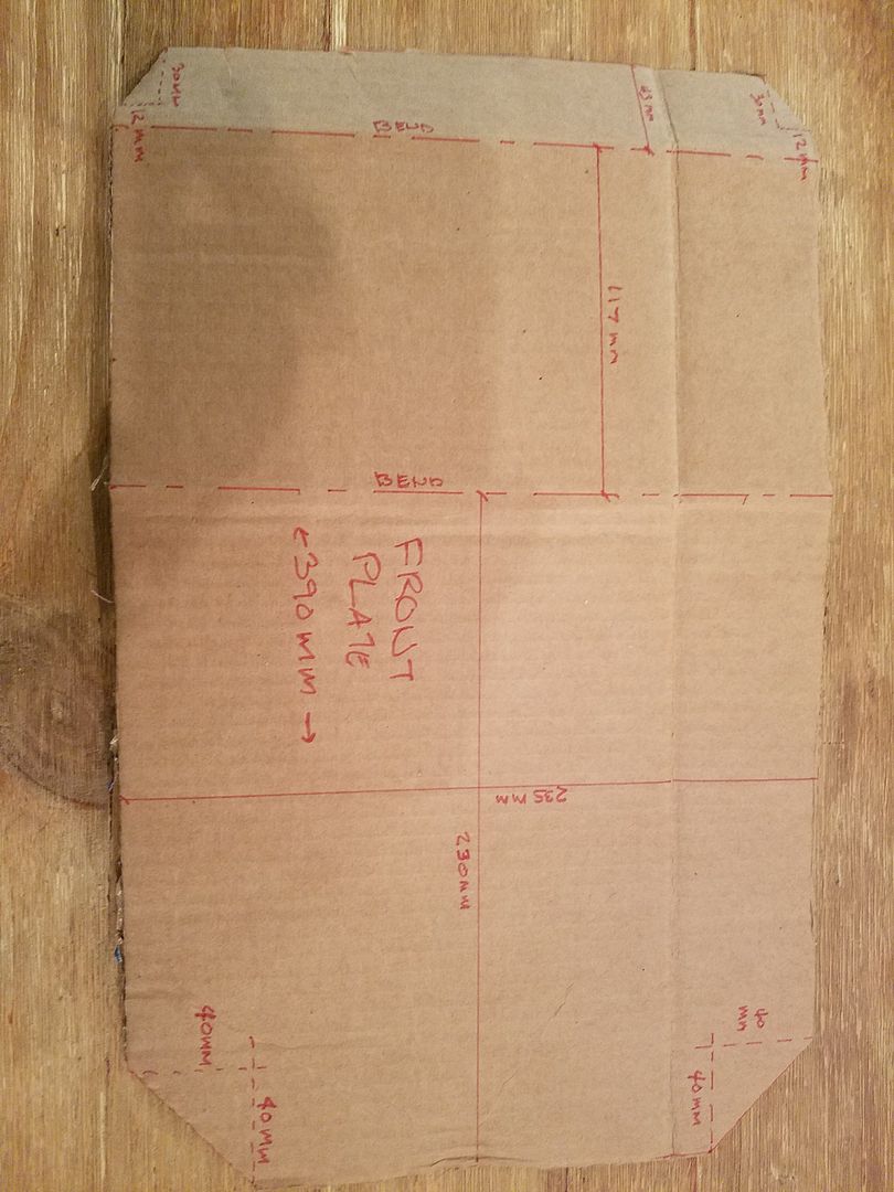
I then traced the template, confirmed the measurements, and cut out the piece from the PVC Foamboard.
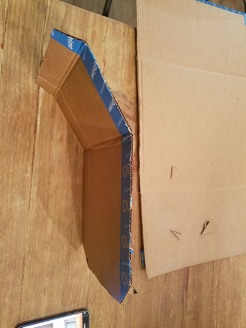
I again used the heat gun to bend the plate (panel) where I needed to.
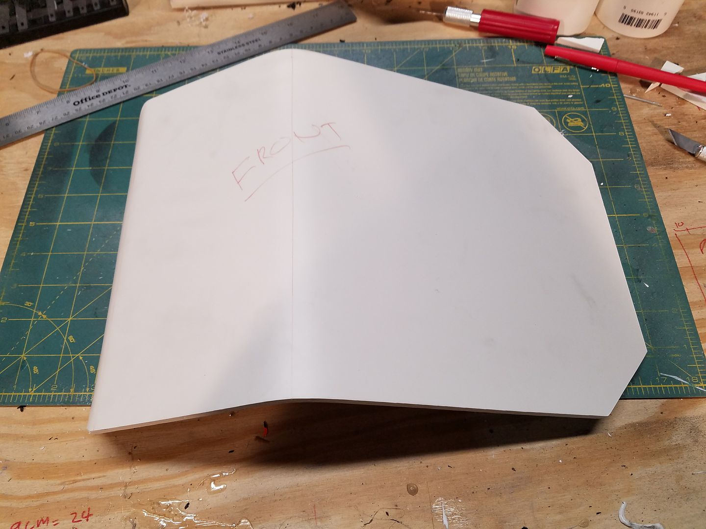
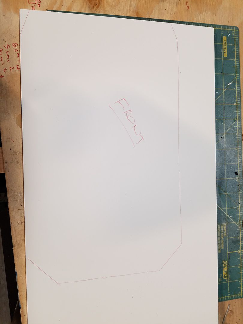
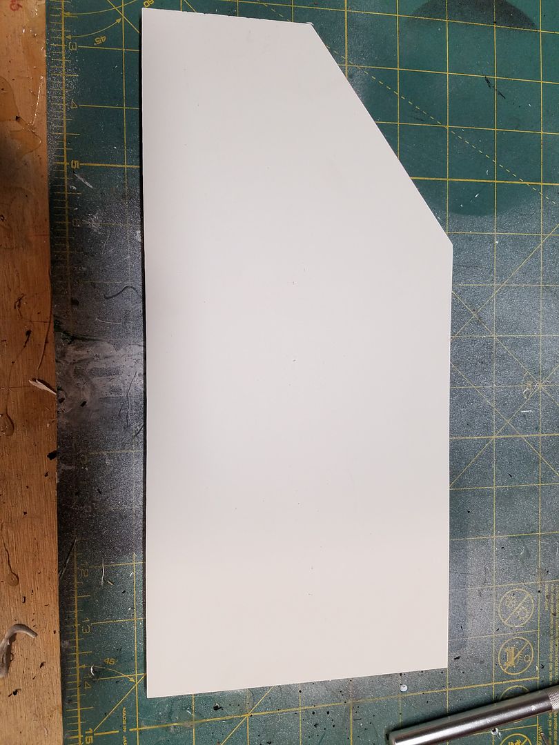
At this point, I measured and traced out the 2 side pieces that go with this face plate. Use this template for both plates. Only need the notch in 1 plate.
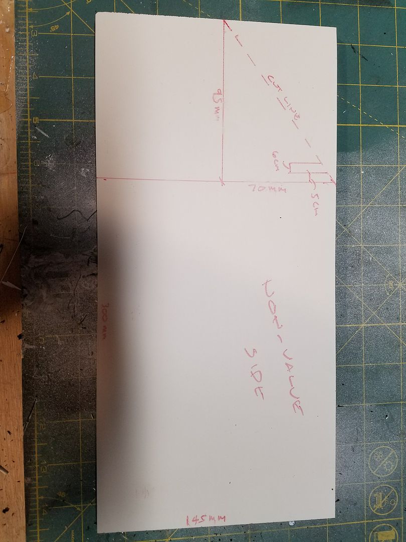
I am waiting to cut the notch until I can confirm placement.
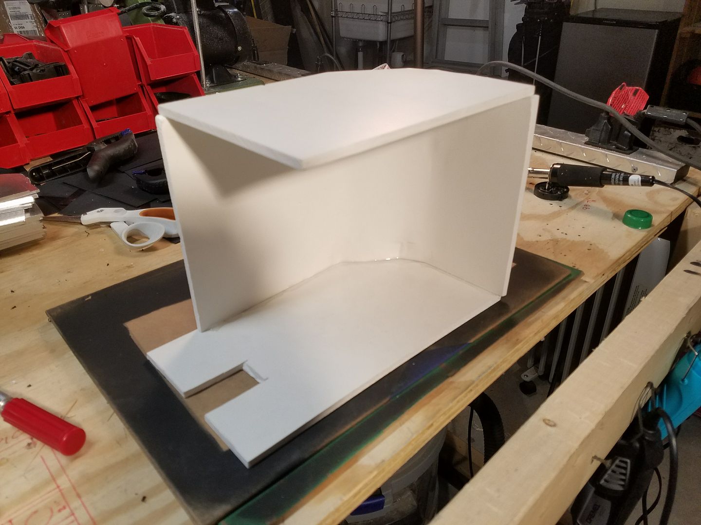
Next cut out 2 identical pieces that will go on the face plate. At some point, I will label the pack and reference the pieces so this is easire to follow. Measurements will also be clarified and added to all drawings and text. Since this is a work in progress, I am having to do things, via trial and error.
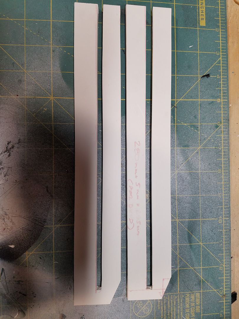
These 2 pieces will be bent 90 degrees to allow for the proper sizing. Next time, I will not bend these and just create 3 separate pieces, in lieu of 2.
Bending is made possible by applying heat to the PVC Foam board via heat gun.
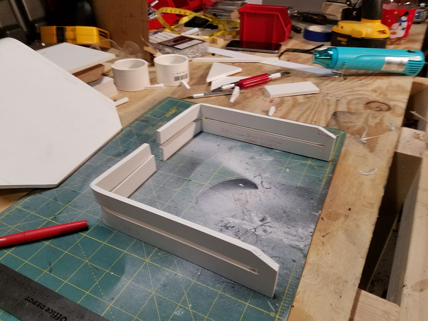
I then slid these onto the face plate and allowed for 15 mm around the edges.. Glued, taped, etc....
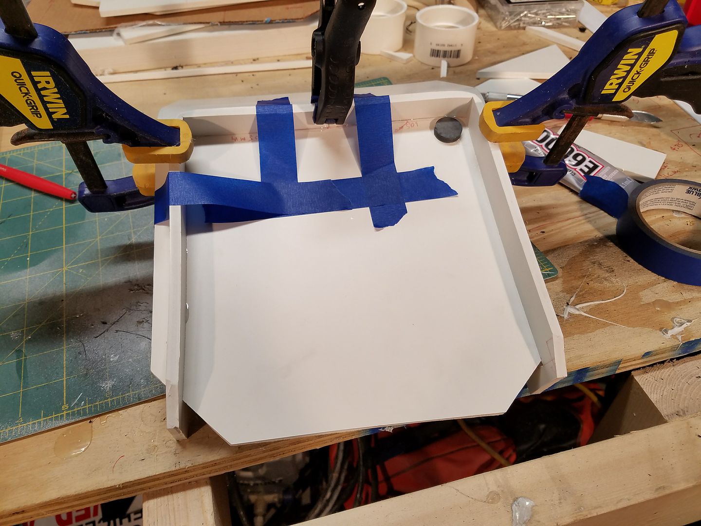
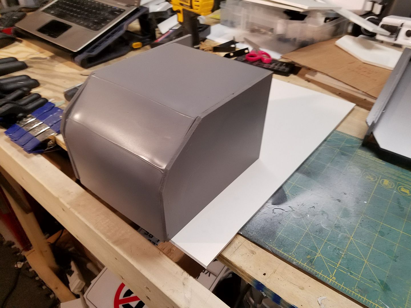
Once the glue dried. I sanded it down and prepared it for painting. For now, I applied 2 coats of gray primer paint (flat).
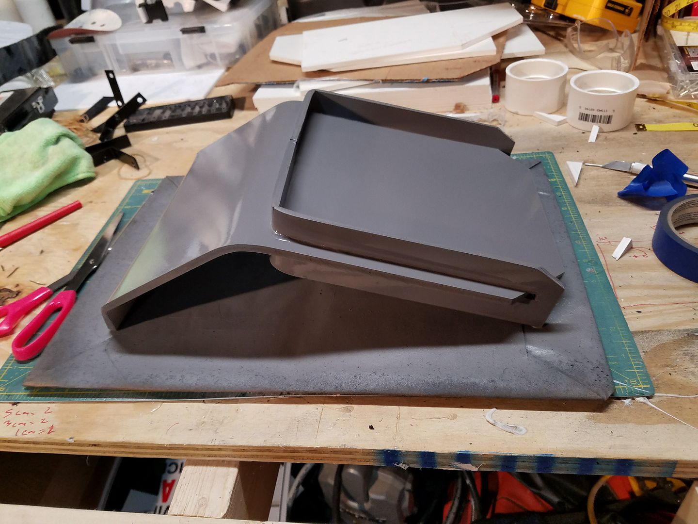
Ok. I have spent the last couple of days working ******* this thing.
First thing I noticed was that I put the side panels on backwards. The part with the notch needs to be on the left side of the pack. Below is the corrected version.
After I corrected that mistake (this happens when working on a prototype for future builds). I cut out the back plate 500 mm x 250 mm.
I then cut out the 215 mm x 58 mm section at the bottom right.
Then glued the finished portions to the back plate.
I then glued the previously cut top angles to the back plate. (only 1 shown below)
When I test fit the top plate over these, it appeared they were too long. Therefore I had to remove them and cut them down.
At the same time, I shortened the back plate by 75 mm and glued the two angle pieces back on. You will notice the fins and some other pieces are on the left side of the photo. These will be discussed in another section.
For what I am calling the access hatch on the face plate, I created this out of the 1/8" PVC board and cut out a 14 cm x 13 cm rectangle. I had actually cut out a hole on the face plate at 13cm x 12cm, however, I could not get it to function correctly. So for this prototype I am going to keep the access hatch on top of the plate instead of flush. I will see if I can make an operational hatch for Version 3.
For the upper small "Name Plate" on the face plate, I cut a 4 cm x 6 cm rectangle out of the same 1/8 pvc board.
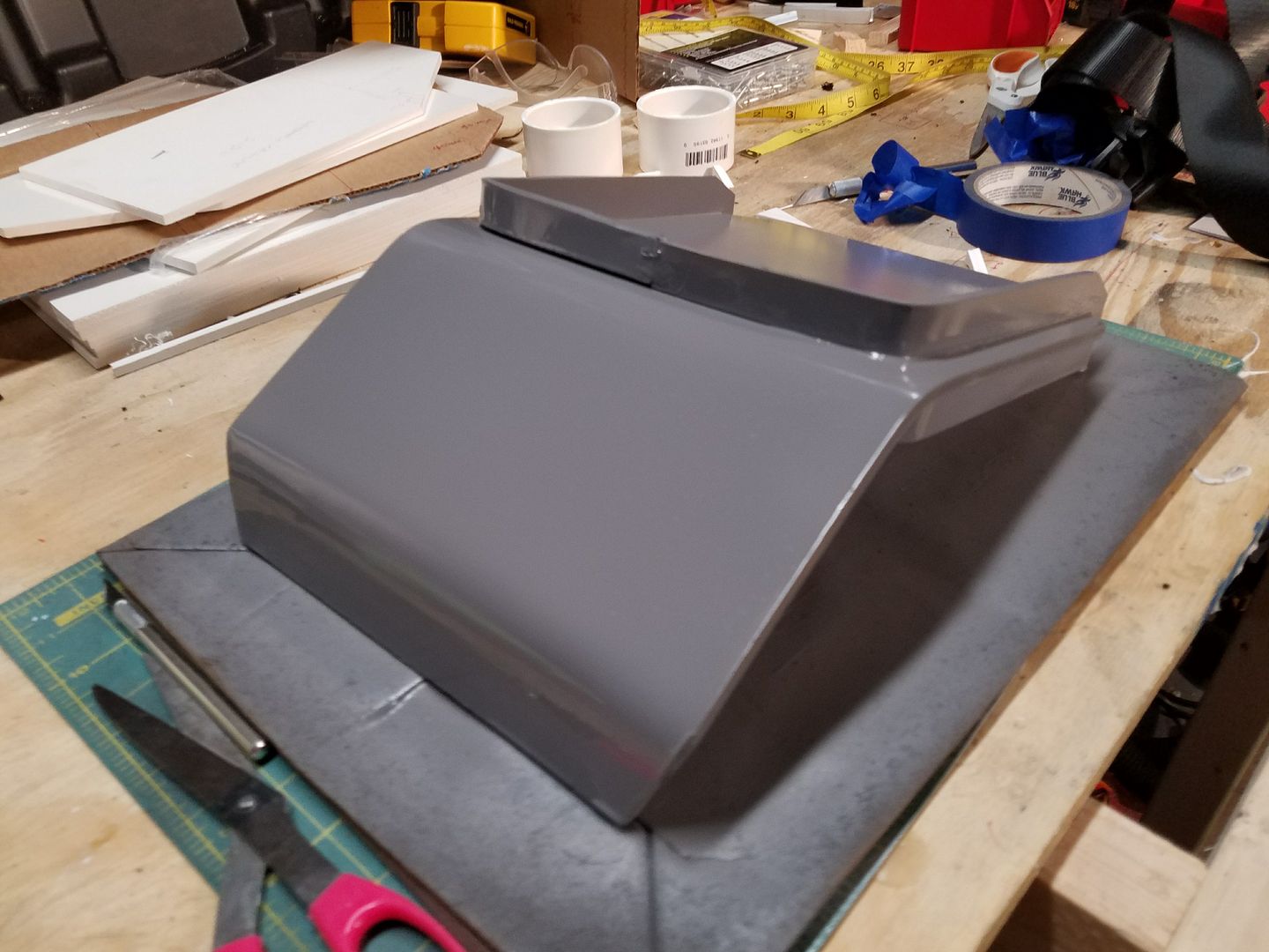
These are the 2 plates after 2 coats of the flat gray spray paint.
Here is a picture with the plates attached.
-
Added the following to the FINS SECTION above.
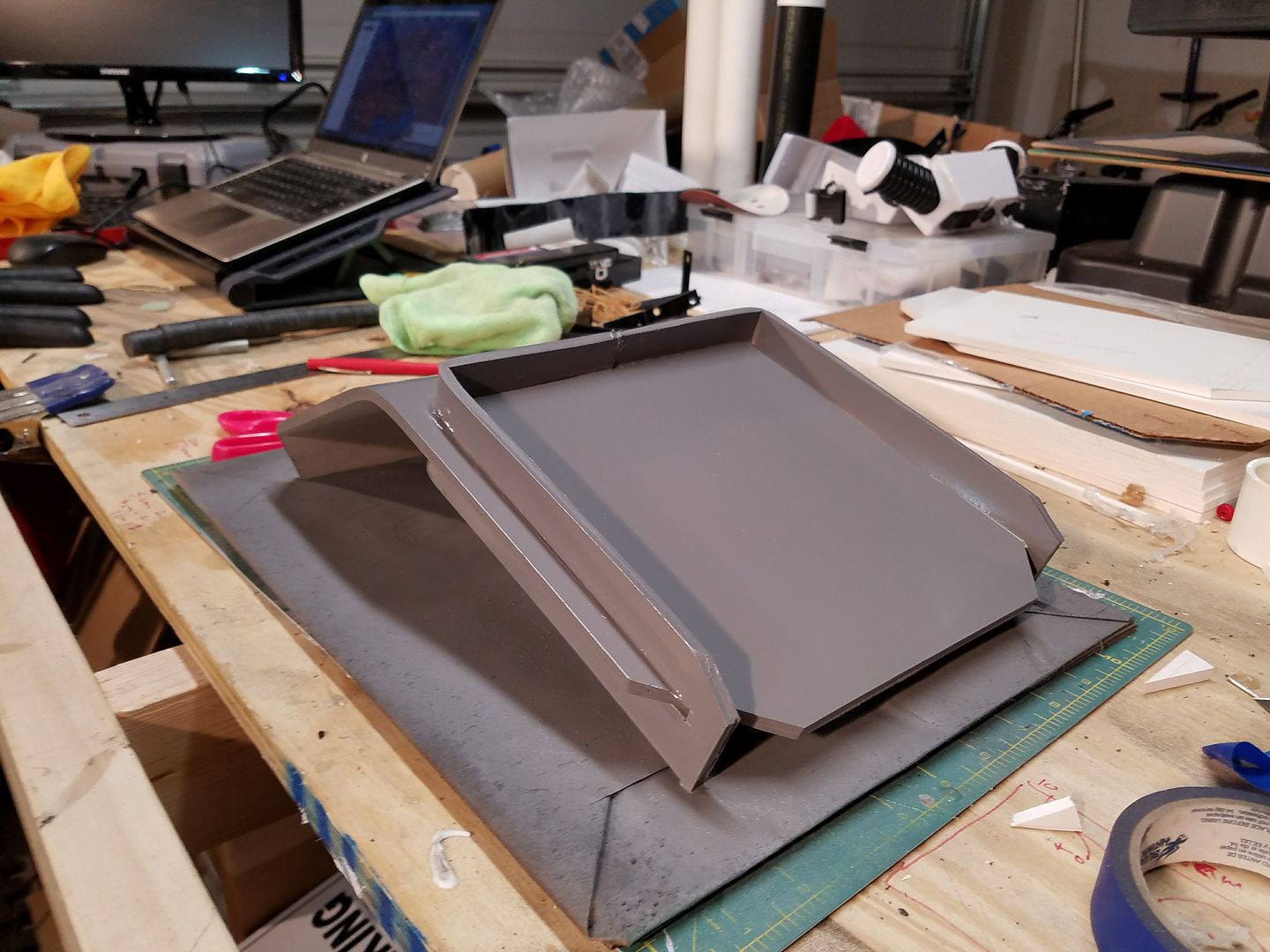
I wanted to go ahead and test the paint adherence to the acrylic, so I painted 4 fins.
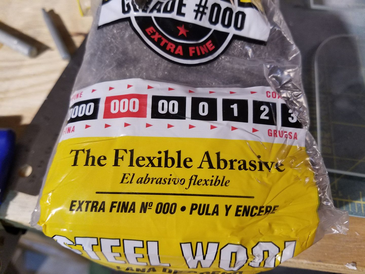
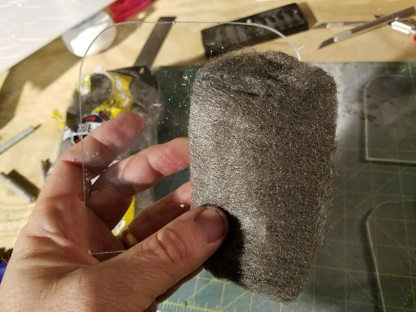
First, I cleaned off the plexi glass with very fine steel wool to make for a smooth surface the paint would stick to.
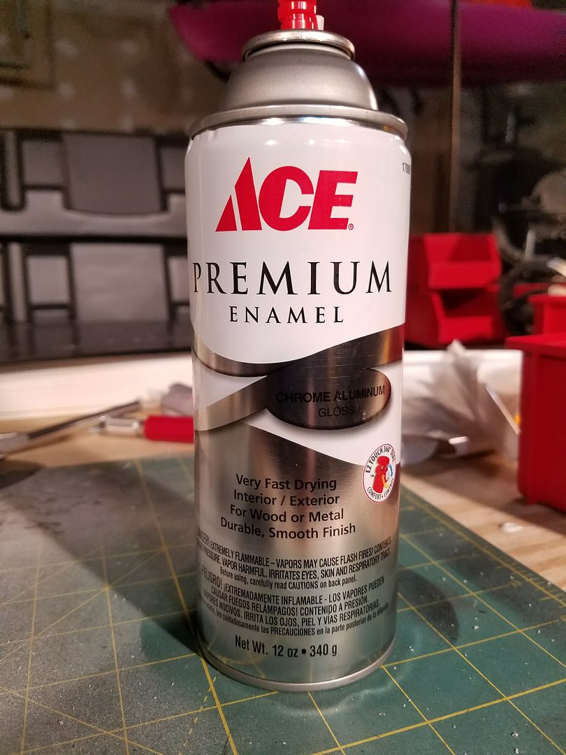
Next I used a premium Chrome Aluminum Gloss Spray Paint from a local hardware store.
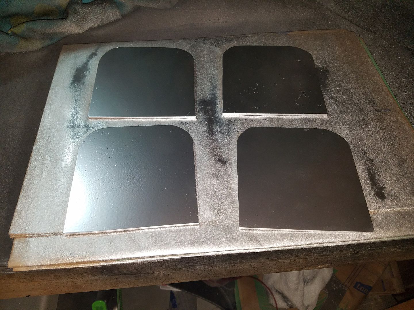
I laid the fins out to paint 1 side at a time.
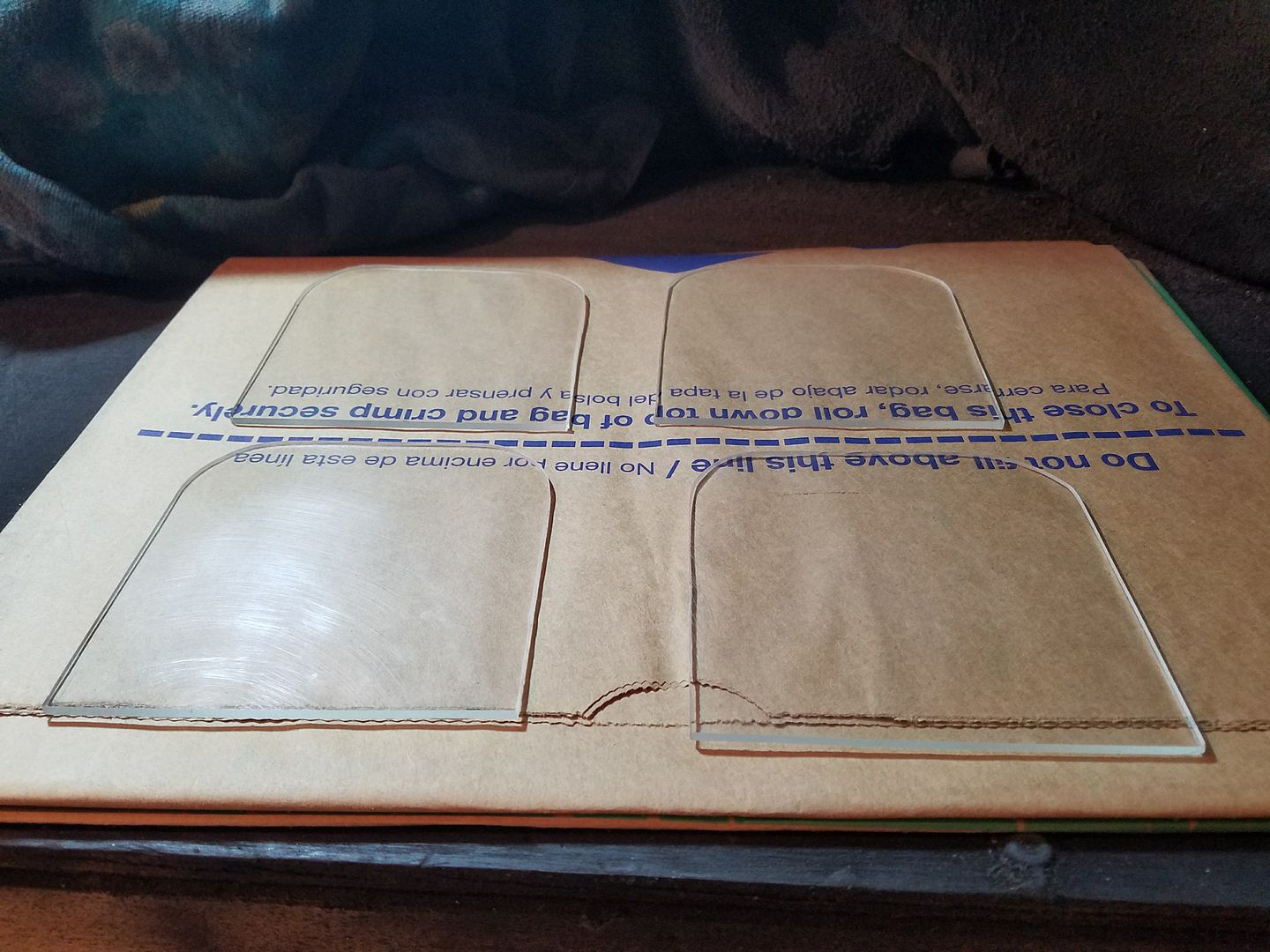
I then applied 2 coats to each side. This is what I ended up with. I am happy with this result and will continue with this method for all remaining fins. Unfortunately, I did not order enough of the material, so I will have to wait for it to come in.
Once I get the remaining material in, I will finish this section.
I wanted to go ahead and test the paint adherence to the acrylic, so I painted 4 fins.
First, I cleaned off the plexi glass with very fine steel wool to make for a smooth surface the paint would stick to.
Next I used a premium Chrome Aluminum Gloss Spray Paint from a local hardware store.
I laid the fins out to paint 1 side at a time.
I then applied 2 coats to each side. This is what I ended up with. I am happy with this result and will continue with this method for all remaining fins. Unfortunately, I did not order enough of the material, so I will have to wait for it to come in.
Once I get the remaining material in, I will finish this section.
Crookknight's Sandtrooper Armor and Pack Build Thread
in Sandtrooper Armor
Posted
Finally getting back to my build. Worked more on the shin armor today. I finished trimming down the remaining pieces, then I cut the cover strips for the shins. Each one was cut to length of the shin and 1" wide. Once cut, I sanded them down and glued to the shin armor. I glued to one side of each shin (total of 2). Since this is a point of contracting and expansion I just glue, with E-6000 one side at a time and allow for 24 hours to dry. In order to ensure it holds in place and adheres as much as possible, I use many rare earth magnets to hold them in place.
As you may be able to tell, I am not going to overlap the shin armor.