mr paul
-
Posts
22 -
Joined
-
Last visited
-
Days Won
4
About mr paul

mr paul's Achievements
(1/14)
18
Reputation
-
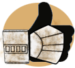
 Here is a comparison of the NGT 12ft float master (top) against the the Avanti Precision X (bottom) The NGT is overall a little wider diameter and the line guides are slightly out. The tip has been cut off from my Avanti already hence why the end is missing. The whipping on the NGT is gold instead of red and the eyes are a different diameter but overall a good substitute rod for the antenna.
 -
Here is a comparison of the NGT 12ft float master (top) against the the Avanti Precision X (bottom) The NGT is overall a little wider diameter and the line guides are slightly out. The tip has been cut off from my Avanti already hence why the end is missing. The whipping on the NGT is gold instead of red and the eyes are a different diameter but overall a good substitute rod for the antenna.
-
I have all the original parts of the Rogue One pack ready to go on this Mimban variant. I am very interested to see if anything has changed on the back of the Han pack. I hope there will be good reference at some point however I am very aware that we may never get the same exposure on it as the R1 Crystal Pack.
-
These 2 images from the trading cards seem to show a black shoulder strap on the right and a camouflage on the left. The r1 hook greeblie is present and the frame looks to be the Swedish M75 again. Also can possibly see a little alice pack poking out the back but unsure. Weather shroud on top appears to have the same webbing and cam buckles as before. I have all the correct parts of the R1 pack sitting here ready to go so I am very interested to see if the rear of the pack is the same as R1 or whether it has been tweaked or changed. Looking forward to more pictures. In the second picture the trooper has the poncho on and the weather shroud is still attached to pack so bang goes my theory on the them being the same thing.
-
SOLO - Mimban Trooper CRL Development
mr paul replied to henselmonster's topic in Mimban Trooper Armor
I must admit personally I am more excited for the back pack than the trooper. As you can imagine Ireachy and Myself have spent a lot of time taking to pieces the R1 Crystal pack and are very much looking forward to doing the same to this new variant. Already we have noticed something "odd" about the pack so are really looking forward to getting our teeth into it. -
There are no leads on the weather shroud (bedroll) at all. It has no features that can be distinguished. Myself and ireachy have speculated that it may be a poncho. Others have guessed it could be a pup tent. There are no seams or stitch lines visible so it has not been identified as yet. Your best bet is to scratch build one as we have done then shape and colour match to suit. Information regarding the assembly of my weather shroud has just been added to the thread. I believe member Bradberry is based in the States and he ordered a pair of NGT Floatmasters the other day. It may be worth chasing him up to find out his source. Your chances or finsding the Avanti Precision X are now very slim to none as it is no longer produced or sold anywhere. It is obsolete. They are even rare to find on the secondary market as they were only ever cheap made rods. Thanks for following our thread and pleased you are building one
-
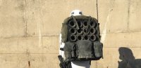
A 360 view of my current pack. This is built to the spec of the thread above but it has the longer antenna whereas the SWCE pack had the shortened variation. I plan on stripping this down and re-stuffing the alice pack to create a more squared off shape. I hope to make it a little lighter in weight in the process. While the pack is dismantled it will give me the opportunity to exchange 2 of the original webbing loops on the bottom, inside corners of the pack with the correct polypropylene webbing.
-
The NGT 12ft float master is very close in size and detail. It comes with gold coloured whipping around the guides but this can be coloured red marker pen. I am still looking for an exact match to the Avanti Precision X.
-
Crystal Patrol Field Pack discussion topic
mr paul replied to dutchy's topic in Crystal Patrol Field Pack
Kyber Sandtrooper makes no sense at all to me. Crystal Patrol Stormtrooper or Crystal Patrol Trooper would be the most accurate name for them. Their kit has nothing to do with the environment they are occupying and directly relates to the activity they are involved with i.e. confiscating Kyber Crystals. It is "Field specific kit" that is the load out of a "standard stormtrooper" to quote the Rogue One Visual Guide. Changing the name too much seems like a little bit too much artistic license IMO especially as it is defined quite clearly for us in the vis guide. -
More of the build thread has been added. I will get some more up soon. Apologies for it taking so long.
-
I am posting the original thread up in one big lump and when I have it all up to date we will post all our latest findings and alterations in new posts.
-
This thread will look at the Rogue One Stormtrooper (R1 TK) back pack as seen on display at Celebration Europe 2016 (CE) in London. It is recognised that at least 3-4 R1 TKs have been seen wearing the back pack in the trailers, CE sizzle reel, and various promotional material. This build is concerned ONLY with the CE R1 TK pack, as this is the most documented and readily scrutinisable prop; due the vast online reference library generated by attendees at the convention. It is possible that there are variations in the builds of other packs used on screen in the final theatrical cut of Rogue One. We will also mention obvious variations in wearing the pack such as: placement of the pauldron over or under the right shoulder strap, and inclusion or omission of the detonator cylinder. The investigation behind the thread has been on-going since the pack was first seen in July 2016 at CE, with an increased focus over the last few weeks. The research is primarily a collaboration between four individuals: Paul Prentice (mr paul), Chris Trevas (lonepigeon) of ‘Parts of Star Wars’ (PoSW), Jody Williams (ht7), and myself Ian Reach (ireachy). Other notable contributions regarding certain parts have come from Andy Rodgers of ‘The Shed of Glittering Delights!’ (SoGD) Facebook group, and also the initial thread started by TK Gino here on ‘1st Imperial Stormtrooper Detachment’ (FISD). As well as significant time and effort researching the pack and its components, the team has also purchased found part components, along with numerous samples of ‘close to’ parts and sub-components, in efforts to build the most accurate / authentic pack possible. Many a 'blind alley' has been explored, with a discard pile of ‘not quite correct’ parts steadily building over the last couple of weeks. The build is based Mr Paul’s version 2.0 pack, as he and ireachy broke-down his version 1.0 pack based on the team’s detailed observations. The thread is intended to share the knowledge developed by the team, help others avoid mistakes we have made, and to act as a guide to building the most authentic R1 TK back pack possible. Of course, you can take as much detail, or as little, from this thread as you wish to inform your own builds, but we hope to present a compelling break-down and guide to building the prop. Most of the found parts are still readily available, and certain ‘hard to find’ parts will be available for sale from the team members as we proceed with the thread (it is possible that the team have found original suppliers of certain parts to Lucasfilm Ltd (LFL), although 100% corroboration is difficult to ascertain). This said, it should be noted that three of the four team members live in the UK where the supply of parts may be easier to source directly, than in other parts of the World. The build thread will be broken down into distinct sections, focusing on a discrete component, or sub-assembly, of the pack: 1. Frame; 2. Soft pack – the Alice Pack; 3. Ammo box; 4. Canvas roll; 5. Antenna; and 6. Shoulder straps, including the RAF K-Type dinghy quick release greebie. Each section will be supported by references and evidence, and we will clearly indicate where we feel the evidence is weak and the team has extrapolated our own ideas and interpretations. There are a few limited cases of these extrapolations which could result in deviations from the actual CE R1 TK back prop. Most however are associated with the area of the pack that lies between the TK back and the back of the frame, ammo box and soft pack i.e. parts not seen in reference material, but also hidden from general view on the final pack as worn. The separate sections will describe details about the found parts, where known, and these will also be confirmed / published on the PoSW page as we progress. It will provide in-depth assembly observations, as there are significant specific details that have come to light, and will also cover dyeing methods and weathering techniques. As a teaser, here are some details that have come to light which we will be discussing, and have incorporated to the build: 1. The Frame This first build section of the thread will look at the FRAME used on the Rogue One Stormtrooper (R1 TK) back pack as seen on display at Celebration Europe 2016 (CE) in London. There has been a lot discussion about the frame since the weekend of CE, and alongside the Ammo Box, it was one of the first parts to be identified. It was rapidly posited that the frame belonged to a 40/45 (or even a 70 litre) Swedish back pack with frame model number LK35 or M75: https://www.facebook.com/PartsofSW/photos/a.936085596514055.1073741860.193037424152213/957124981076783/?type=3&theater Haglofs made a civilian version of the LK75 until the late 1990's, with early models having cotton webbing straps, and later version with nylon ones (Lars E Grimstad, on PoSW). However, clear pictures of the CE back pack frame, especially detailed ones are very difficult to find. Primarily due to the fact that it is obscured by the trooper and the rest of the actual TK pack itself. However as seen in the pictures above, the frame is mounted outside of the attachments. The frame is not within the Alice pack. The LK35 and the M75 packs are almost identical, and discussions on various forums have shown that suppliers themselves do not appear to realise the distinctions between the two packs. Reading through discussions it has become apparent that LK35s have been sold as M75s, and vice versa. Pictures listed with a supply of LK35s can be M75s, and more worryingly many M75s listed with accurate M75 pictures are turning out to be LK35s. It appears the only way to mitigate this mis-identification will be to visit a surplus store in person and sort through the stock. The pack below is an LK35… It is relevant to note that the soft part of the pack and the shoulder straps are discarded. They are NOT part of the CE TK back pack, and NONE of the webbing or buckles are used in the build (evidence to support this will be discussed in greater detail in subsequent build sections associated with the Alice pack and the canvas roll). The photographs below show a comparison between the LK35 and M75 frames… The height of the frame posts at the top of the frame to which the soft part attaches; o ~45 mm on the LK35; o ~28 mm on the M75; and · The shape and colour of the frame post end caps; o Linear and green on the LK35; o Slight inverted cone shape and light grey on the M75 - Note that there are apparent colour variations and some correct shaped end caps have been supplied in black, not the light grey; The shape, angle and welding points of the webbing attach mounting at the bend of the frame’s ‘shelf’; o Nearly perpendicular to the frame back and shelf on the LK35, and welded to outside of the frame; o More acutely angled in relation to the frame back on the M75, and welded in-line with the frame; Slightly larger / deeper shelf on the M75 compared to the LK35; o The LK35 shelf depth is ~90 mm; and o The M75 shelf depth is ~105-110 mm These details are important, as analysis of reference photography for the CE back pack, primarily associated with the posts and end caps and the webbing attachment mount, has allowed identification of the frame type used on the prop. The details seem to indicate that the correct pack frame used on the CE back pack is the M75, NOT the LK35. The M75 ‘feels’ slightly more robust and bulky than the taller LK35 – although this is purely a subjective feeling. This said, do note that certain M75s have been received with the correct shaped end caps but in black, not the light grey seen on the CE prop. The picture below shows the post end cap is grey, not the green seen on the LK35. Also, the frame section tubes are ~14 mm diameter, and the height of the post, from the horizontal top bar of the frame, is approximately twice that measurement i.e. close to the 28 mm of the M75 frame. Certainly not the 45 mm of the LK35. We also know that the webbing on the canvas roll is 1” / 25 mm width webbing (this will be examined in greater detail in the canvas roll build section). The distance from the top horizontal bar on the frame is nearly exactly the same height as the webbing width (on the canvas roll). This means that there is little more than 1" / ~25mm left on the frame upright from the upper horizontal bar to the end of the post and top of the end cap = ~28 mm = M75. If the frame was an LK35, then the top of the post (from the top horizontal bar) would be closer to 2 x width of the webbing (on the canvas roll). This appears to validate the hypothesis that the frame is the M75. This picture shows that the weld spot for the webbing attachment mount does not extend all the way across the frame outside as is evident on the LK35. Rather, it is aligned with the frame and is barely discernible. It is important to note that the condition of field-issued and unissued frames is highly variable, and on-line pictures show large range of dings, scratches, bangs, chips etc. These are evident on the CE frame (see picture below) and the frame was not repainted for use on the prop. The webbing back supports (that are tied under tension horizontally across the frame in two places) are not dyed black. They are left untouched and original colour – well certainly there is photographic evidence that the lower back support webbing was left as per original frame. The team does acknowledge that the evidence base to support the identification of the M75 is not over-whelming from analysis of the reference material alone. However, we believe comparison of the two frame types side-by-side supports our identification of the M75 as the pack frame used on the CE prop. The frame appears to be available widely from army surplus stores and online shops across the UK, Europe and in the United States. However, it seem to be a gamble to whether you receive an LK35 or M75, even if the pictures on the site indicate one or the other. Colemans cites LK35 on its website, but the picture is an M75, and received kit appears to be either the LK35 OR the M75: https://colemans.com/…/swedish-military-backpack-with-frame/ LK35s can be bought cheaply in the UK from Military Mart: http://www.militarymart.co.uk/swedish-army-lk35-rucksack.ht… More links will be added when sourced but a suitable online search should turn up the pack. If 100% CE prop accuracy is not a concern, and as the differences between the two frames is minimal, then there is an easy mod that can be done to the LK35 to bring it much closer to the M75. The end caps can be removed, and the posts cut down, using an angle grinder or Dremel-type tool, to 28 mm. The end caps can be painted a light grey and then replaced. It is possible that a plastic or rubber end cap with the correct inverted slight cone shape, and the correct M75 colour, could be purchased on-line, although the team has not investigated this possibility. As a nod to the release of some awesome R1 posters and the latest trailer last week, the team thought that we should cut across the build thread and divulge what we have found out about the metal hook greeblie used on the left shoulder strap of the pack. Our observations will again relate to the CE prop. However we do know that this greeblie is present on all packs seen in trailers, the sizzle reel, and promo pics, along with the Hot Toy. As stated, in keeping with the rest of the build thread, the observations presented here are based primarily on the back pack seen, and photographed, at Celebration Europe 2016 (CE). The various trailers and the sizzle reel indicate that the hook greeblie is present on all of the Jedha large back packs seen to date, although shots from these sources are not detailed enough to contribute to any detailed analyses of the greeblie itself. Towards the end of August / beginning of September 2016, the hook greeblie was discussed / identified (as far as possible) on various forums including: ‘The Parts of Star Wars’ site ‘The Shed of Glittering Delights’ Facebook group, and on ‘FISD / whitearmor.net’. The hook greeblie is believed to be a quick release connector associated with RAF and RN 1940s onwards K-Type pilot dinghy pack. Three similar quick release units were used on each dinghy pack, to attach the pack storing the uninflated emergency single person life raft (dinghy) to the pilot / observer harness rig, or to ejection seats 1950s onwards. The K-Type dinghy was used in fighter aircraft or by observers in those RAF aircraft where the large multiple crew round dinghy was not practical. During the Second World War the K-Type dinghy pack was intended to be used by fighter pilots and observers wearing the seat type parachute, replacing the normal parachute seat cushion. They were thus referred to as the ‘seat pack’ as the pilot actually sat on the dinghy pack whilst in the aircraft. The team believes that one of the quick release clips attached to the 1941 pattern life jacket, and a similar quick release (not associated with K-Type pack) was also associated with the parachute activation handle seen on the waist belt (near 12 in image above). The Type A pack contained the dinghy and equipment with a readily detachable top panel connected to the dinghy by a painter, and to the pilot by a webbing strap. That webbing strap was attached via a quick release unit. Various types of K-Type dinghy pack are known with Type A, MK.II. used up to around 1942-44, and MK. III.s used 1944 onwards. The MK.III.s and Type Bs had additional features such as extra pockets for extra CO2 inflators and different arrangements of storage pockets etc. The quick release unit used for the K-Type dinghy pack consists of two components: · A male component consisting of the quick release mechanism at one end and a T-bar for attaching to straps on the K-type dinghy pack; and · A female T-bar component. The quick release unit used for the CE hook greeblie also consists of two components: · A male component consisting of the quick release mechanism and a T-bar for attaching to straps on the K type dinghy pack; and · A female spring-loaded hook component. It is important to note that the team has NOT been able to locate ANY reference pictures showing the female hook component attached to K-Type dinghy packs or RAF / RN pilot / observer harnesses. However, the use of the ‘seat packs’ continued with RAF early jet aircraft (1950s), although the dinghy pack evolved into the Aircrew Personal Survival Pack (PSP) container over time which housed everything for pilot survival, including the dinghy in a Glass Reinforced Plastic (GRP) box, but still under-slung on the harness. It is possible that the female hook component came into use once the PSP and GRP box became the standard, allowing a more efficient quick release system attaching to clips on the GRP box? The team is currently approaching the Imperial War Museum, Duxford, to see if they are able to further identify the female hook component of the CE hook greeblie. Component Details As stated, the quick release unit used for the greeblie consists of two components: male quick release unit + female hook component. Male Quick Release Component The male component of the quick release unit appears ubiquitous across many 1940s+ RAF and RN flight gear. It is known to have been used on the K-Type dinghy pack, along with 1941 pattern seat parachutes. The male component has no readily identifiable maker’s mark, but most samples do have either a Patent Number on them: Pat No. 478506, or the following ID No. 27C/2157. This is located around the top collar of the corrugated quick release pull mechanism near the T-bar end. The team has so far been unable to further identify the male component, although it does appear a ubiquitous 1940s-1960s RAF / RN quick release mechanism. Female Hook Component The female hook component does have a maker’s mark and part number: AML 115. Research by lonepigeon and mr paul indicates that AML refers to the maker: Aircraft Materials Limited. AML is now part of Airborne Systems, which still makes very similar equipment, although no longer produces the actual female hook component used for the greeblie (as far as we can ascertain, and certainly not in the 1940s-50s form). Review of the team’s collective sample of quick release units has revealed both subtle, and more distinctive, variations between various female hooks. Most notably, some male quick release and female hook components appear to be cast in a silver finish metal whilst others are cast in a metal with a ‘gold’ finish. The female hook is cast metal with the maker’s mark consisting of a cast alphanumeric on one side of the hook stem – AML115. In general the ‘5’ is exceedingly indistinct, although some samples do show this character, most often the silver metal versions which appear to retain a sharper moulding than the ‘gold’ hooks. On the reverse side of the stem a V can discerned. However, some hooks also have the maker’s mark and part number stamped onto the outside neck of the hook. The stamp is AML115, so it appears that these hooks just have a more clear presentation of the information we already know concerning the maker – AML – and the part number – 115. Following the mark AML115 on the neck there is also a stamp mark. This is a circle containing a stylised AML over the numeric 51. The team has not been able to identify the significance of the numeric 51, however this could be a year stamp e.g. 1951, with those hooks not displaying this feature being manufactured prior to 1951? However, this is conjecture, we do not presently know, and this is one of the questions being asked at the Imperial War Museum. From the photographic material available of the CE prop greeblie it is impossible to determine if the maker’s stamp and part number are present on the neck of the one used on the CE pack. There is another, slightly different female hook available. This has the same version of toothed hook jaw and spring mechanism as the previous types described. However the main hook stem and body has some noticeable variations. These are: 1. Appears cast in a different metal type, it is less ‘granular’ with an almost machined finish; 2. The ‘step ’between the stem (which attaches to the male quick release component) and the ‘hook’ is much less rounded, more angular then on the other hooks; 3. AML 115 is very clearly and cleanly stamped onto the face of the hook; 4. There is a maker’s mark stamped above the AML 115 mark; and 5. There are two parallel lines running around the stem of the hook. Conclusions Further analysis is required to see if there are any maker’s stamp details or part number mark on the outside neck of the CE prop greeblie. Analyses of trailer and sizzle reef footage have not been able to provide any answers, and the film footage is also unlikely to provide the required resolution of detail. Only close-up, detailed photographs of actual screen used prop packs are likely to provide any further information. Regardless, the CE prop has been identified as best as possible, and the male quick release and AML115 female hook are the found parts used on the CE prop, and presumably the other Jedha large back pack props used in the film. The team has exerted much time, effort, and funds to try and track down a supply of the CE hook greeblie. The fact that the found part originates in the UK, as with many Star Wars found parts from the OT, means that we have been exhaustive in our efforts. This has led to contact with a supplier with known previous contact with, and supply to, films such as: Prometheus, Spectre, and The Martian. Mr paul and ht7 were recently able to visit the supplier in person, and on the back of the visit the team were able to purchase the supply of the AML115 hook and male quick release units that the supplier held. The team's vision is to secure the only known supply, and limited numbers of, the found part and enable sales to prop builders, film aficionados etc. We are confident we have identified the correct fishing rod that is used as the antenna on the Celebration TK field pack. Many hours were spent trawling through images of angling equipment and we are happy to have found it. The Avanti Precision 12ft 3 piece float rod. We will present an examination of the antenna prop whilst comparing it with what the team now believes is the found part. We will focus on diagnostic features seen from the CE reference material. Originally there was a hypothesis that the antenna is an altered / modded military radio antenna, as used on jeeps, Land Rovers etc., ‘Telefunken model Ms 116/117/118’. Discussions also looked at the possibility that the antenna is a fishing rod. The ‘eyes’ / guides that the tubing on the antenna is threaded through were rapidly agreed to be fishing rod line guides (hereafter referred to as ‘eyes’). The team has discounted the use of a military radio antenna as the prop. This is based on the diagnostic features listed below, and also relates to the relative rarity of these parts and their prices; most examples fetching prices in excess of £50 and up to £100+. This did not seem to be the type of part that is used by Star Wars prop builders, for what will effectively be background props. As we know from experience such items in the OT were built from cheap items such as seed trays, plumbing parts, Tupperware and wet wipe tubs e.g. the sandtrooper packs I in Episode IV. The prices did not stack-up for us. Detailed review of the available reference pics has convinced the team that a fishing rod was used for the prop – a common and generally cheap part to source for prop building. The reference material shows several distinct diagnostic features that we have used to identify what we believe is the found part. These diagnostic features are: 1. Texture of the antenna; 2. Details of the cut end; 3. Antenna outer diameter; 4. Details of the eyes and their spacing – this also relates to antenna length; and 5. Eye whipping / ‘wraps’ and the red ‘flash’. Texture The CE prop antenna has a distinctive texture that appears to be a type of black carbon fibre wrap. The carbon fibre has a rippled texture running around the antenna and is evident on a lot of modern fishing rods. This observation is based on referencing online pictures and also personal observations made by team members looking at rods in angling and outdoor recreation shops. The pictures below show the CE prop and then the found part. Open (Lower) End of the Antenna There are several reference shots of the CE prop that show the bottom end of the antenna. From the reference material the antenna appears to be hollow with a grey colour associated with the end. When the found part fishing rod is cut it gives the same appearance as the CE prop. Antenna Outer Diameter We have taken guestimate measurements from the CE antenna. These have been determined using the known width of the webbing used on the canvas roll as reference. The webbing is standard 25 mm / 1”. A marker line was drawn on a reference pic and then transferred to the cut end of the antenna. The outer diameter (OD) of the cut end is approximately one-third the width of the webbing i.e. 7-9 mm as judged using the reference pic. This was the OD range we were initially looking for. It should be noted that the reference materials make it hard to be specific as the lighting at the CE display is problematical and no clear flash photography could be found of this part. Measurement of the found part shows that the OD at the cut end is 9 mm, so within the range we were hoping for from the picture calculations. Mr paul also compared the found part with life-size zoomed reference pics to determine if we had a match. Again, the width of the webbing was used to establish a baseline scale so that the image was not biased by the width of the found part. The measurements of the found part matches-up with the CE prop. Details of the Eyes, Spacing and Antenna Length The eyes on the found part and the CE prop are distinctive. They are new style eyes used for guiding the fishing line from the spool along the length of the rod. On the CE prop they are used to retain the tubing that runs along, and wraps around, the length of the antenna. The eyes on the found part and the CE prop are distinctive. They are new style eyes used for guiding the fishing line from the spool along the length of the rod. On the CE prop they are used to retain the tubing that runs along, and wraps around, the length of the antenna. It should be noted that the eyes on the CE prop have been manipulated to accommodate the tubing and this will be covered in Part 2 when we discuss building the antenna. . The distance between the eyes / whippings was also measured from reference pics using the known webbing width of 25 mm / 1”. From the top of the first eye’s whipping to the bottom of the second eye’s webbing is approximately 10.5 times the width of the canvas roll webbing. This gives a distance of approximately 262.5 mm (10.5 * 25 mm = 262.5 mm). The same distance measured on the found part equals 257 mm. So the rough calculated distance is reasonably close to the measured distance on the found rod. Certainly close enough and within the likely margins of error associated with the rough visualisation. Eye Whippings and the Red ‘Flash’ Reference material from CE clearly show areas where the eyes are attached to the antenna. On fishing rods these are known as whippings and traditionally involved wrappings of line securing the base of the eye. On the CE prop these whippings appear as raised areas securing the eyes to the antenna. What is most notable is that in places at the base of each whipping there is a distinctive red flash / wrap that ‘pops’ in many of the photographs of the CE prop. The found part rod also has this most distinctive diagnostic feature. Antenna This section focuses on the construction of the antenna for the Rogue One Jedha large back pack. The identification of the found part Avanti Precision 12ft 3-part float rod as the base of the antenna prop enabled a relatively rapid build of the antenna itself. The experience that the team had gained through the construction of mr paul’s version 1.0 antenna meant that many of our observations could be rapidly applied and adjusted for the CE accurate v2.0. The antenna consists of just three components: 1. The Avanti Precision 12ft 3-part float rod; 2. Silicon tubing for the ‘cable’ that runs up and is wrapped around the rod; and 3. Small plastic end cap. The Fishing Rod This part has been described in a previous post. It is important to note that the top-most eye at the very tip of the Precision rod is not part of the CE prop antenna. This has been removed. Measuring from the top of the whipping on the next eye down (2nd eye from the tip), the rod is cut off at a distance of approximately 50mm up. The CE rod also appears to have been cut or broken a few mm below the bottom of the lowest most whipping which has an eye, near the end section of the rod i.e. the eye and whipping closest to the open end of the rod top section (the 1st eye counting from the open end). Originally we thought the rod had been cut here, but looking at the pic above it is just possible that the rod may have been accidentally broken? The cut-line is not even, but appears jagged and fractured, and is not what one expects. This build thread is concerned with construction of an accurate CE version of the pack, however, in this case it may be prudent to not actually cut through your rod at this location. We state this as promotional pictures and the Hot Toys version of the Jedha large back pack trooper are now showing that at least one of the other screen seen packs has a much higher (longer) antenna than the one used on the CE pack. Also it appears that the bottom of the antenna rod may extend down further alongside the pack than the one on the CE prop. It may be that part of the upper section of the rod’s middle component may actually be used to boost the antenna upwards, and extend downwards? However this is conjecture at the moment, based on a few images from Topps trading cards and the Hot Toys figure. The team mentions these anomalies as we would hate builders to cut the rod, only to find out after the film has been released that the bottom end of the rod top section should actually be present i.e. only absent on the CE prop due to accidental damage. Of course if you are looking to replicate the CE pack exactly, then a partial cut and then snap will provide an accurate replica. The Antenna Cable This section assumes that the top-most end eye of the Precision rod has already been cut off at – as previously described. To replicate the antenna cable the team have identified black silicone tubing as the closest material used. The cable has to be able to be threaded through the fishing rod eyes, be wrapped around part of the rod – showing a distinctive lay and shape to the wraps – and shows ‘pinching’ as it is threaded through the three top-most eyes. Solid core cable has not been able to replicate these characteristic features. Only silicone tubing has been able to give the correct feel to the cable. During the v1.0 build 4mm ID / 6mm OD black silicone tubing was used for the cable. However, this was not being used with the found part Precision rod, and the eyes used were of an incorrect diameter. Further, the 4mm ID tubing showed a glaring inconsistency when wrapped around the rod. On the CE antenna the wrapping between the 2nd and 3rd from bottom eyes has a distinctive shape and form – the wraps show some flattening of the cable profile, but the general shape is held and there is a slight convex profile across the cable. When the 4mm ID silicone tubing was wrapped around a rod the profile of the tubing does not replicate that seen on the CE prop. The 4mm ID tubing is just slightly too wide and the wraps show a slightly concave profile where the walls of the tubing collapse under the tension of the wrapping. This is not CE prop accurate, it should have a slight flattened convex profile as described and seen above. With the Precision rod, and the size of the eyes, and the diameter of the upper section of the rod, the team suggests that 3mm ID / 5mm OD black silicone tubing is used for the antenna cable. This presents the correct wrap profile, is able to thread through the rod eyes - with some manipulation, see following - and shows the CE prop accurate pinching seen at the three top-most eyes. For the CE accurate antenna 3 metres of the 3mm ID black silicone tubing is a sufficient length. If looking at a slightly taller Topps / HT antenna then it is possible that 4m of tubing will be required. To thread the silicone tubing through the Precision rod, the ceramic-type liners in the eyes will first need to be removed. Without doing this a maximum OD of 2mm tubing is all that can be threaded through the eyes. Reference shows that this removal was done for the CE prop. The lining to the eye can simply, but carefully, be removed using needle-nosed pliers to gently crack and then pull out the liner. A point should then be cut at one end of the tubing to aid with threading and pulling it through the eyes. Start at the 3rd eye from the bottom (now the middle eye on the rod after cutting off the tip) and thread and pull through all of the upper eyes – taking care not to break the eyes - until the CE accurate thread and pinch is achieved at the three top-most eyes. These three top-most eyes are also angled upwards slightly and squeezed closer the plane of the rod. This can easily be achieved through applying pressure using pliers. Again, this should be done carefully to avoid breaking / snapping the eyes. Use reference pictures until the correct pitch and angle is achieved. The cable / tube wrap occurs between the 3rd (now the middle eye on the rod) and the next eye below (2nd eye from the bottom of the rod). With the middle eye facing you and the tubing coming down out of the eye wrap the tubing around to left and behind the rod. This will then give the correct orientation of the wrapping as it winds down around the rod for 13 turns. The 14th turn comes around the right side of the rod (with the eyes facing you) and feeds down through the eye (the 2nd eye from the bottom). Remember to apply enough pressure to the wraps to get the correct shape and profile to the cable and try and ensure that the wraps are tidy and evenly spaced apart. As you can see in the pic above mr paul’s v2.0 antenna wraps still need some tidying Exiting the 2nd eye from the bottom the tubing then falls down the rod and is threaded down through the bottom-most eye and out. The surplus cable will be tucked away tidily when the antenna is attached to the build pack. On the CE pack this was tucked into one of the Alice pack right-hand-side webbing patches. On the HT figure the cable end appears to be tucked into the edge of the ammo box. Some investigative work from slyfox740 over on white armour.net has identified the antenna cable as possibly being black latex surgical tubing as found here. https://www.ebay.co.uk/itm/190607486059?_trksid=p2057872.m2749.l2649&ssPageName=STRK%3AMEBIDX%3AIT Antenna End Cap The tip of the antenna has an end cap. It should be recognised that there is very little detailed reference of this end cap. Identification of the part, or characteristics of the part, have been attempted whilst allowing for the pitch and angle of photographs taken at CE, and making consideration of the lighting at the venue.The team has approximated the outer dimensions and inner diameter using the width of the rod and comparison to top-most whipping. These are: 1. Cap height of 10-12mm; 2. 4-5mm OD; and 3. 2.0-2.5mm ID. We also believe that it is possibly a black plastic style tip rather than rubber one, due to shine and reflective characteristic of the CE prop. The end cap has a noticeable ‘step-out’ from the rod and we believe has parallel sides. Several end caps have been sourced and tried, and investigations are still proceeding with a new focus on CB radio aerial caps etc. ALICE pack I am not going into exhaustive detail regarding the ALICE pack as it has already been confirmed as a found part, indeed it was one of the first parts of the CE pack to be verified. However, there has been some discussion regarding the size of ALICE pack used so there is value in looking at the evidence base for the Large ALICE pack and also points regarding the LC-1 and LC-2 designations, and what, if any bearing these have on the prop. The A.L.I.C.E. system was developed by the U.S. Army during the late 1960s and early 1970s as the standard load carrying system for infantry of that era - All-Purpose Lightweight Individual Carrying Equipment - A.L.I.C.E. It replaced the M-1956 Load-Carrying Equipment (LCE) and M-1967 Modernized Load-Carrying Equipment (MLCE) in 1973. There are 2 components to the system: the fighting load system; and the existence load system. The fighting load was based around a webbing belt and suspenders and designed to be carried by infantry into combat, and at all times. The existence load system was supplementary to the fighting load and was designed to carry additional equipment that a soldier would require i.e. consists of items other than those in the individual fighting load which are required to sustain or protect the infantry rifleman, which may be necessary for the infantry rifleman's increased personal and environmental protection, and which the infantry rifleman normally would not carry. When possible, the individual existence load items are transported by means other than man-carry. Otherwise both the fighting and existence loads are carried by the infantry rifleman. Individual existence load items are usually carried in the field pack (Wikiepedia, 2016). The medium and large field packs are part of the existence load system. Again from Wikiepedia (2016): Field Pack (medium) - The field pack is made of water repellent treated nylon duck and webbing, spacer fabric, and metal hardware. It can be used with or without the LC-1 Field Pack Frame. The main compartment closes by means of a drawstring secured by a plastic cord clamp. A radio pocket is located against the back on the inside. The size of the pack may be decreased for smaller loads by means of three para-cord ties, stitched to the inside bottom of the pack, and three metal D-rings located directly below the internal radio pocket. Three pockets on the outside, with strap and buckle adjustable closures and with snap fasteners for quick access, are provided for miscellaneous items. The top flap has a pocket with a hook and pile fastener tape sealed closure. Equipment hangers are located above each outside pocket and on each side. Drainage eyelets are provided in the bottom of the main compartment and the outside pockets. An envelope pocket is located at the top, back of the pack and padded with spacer cloth, into which the field pack frame is inserted when the field pack is used on the field pack frame. Buckles and straps at each side near the bottom are used for anchoring the field pack to the field pack frame. Two rectangular wire loops located at the top back of the field pack and D rings on each side at the bottom of the field pack are used to provide shoulder strap attachment when the field pack is carried without the field pack frame. A waterproof bag is supplied for the main compartment and each of the three outside pockets for keeping equipment dry. Field Pack (large) - The construction and materials in the large field pack are similar to the medium field pack with the differences being: it is much larger in size; the center outside pocket is larger than the other two main outside pockets; and the addition of three small outside pockets above the larger pockets. The large field pack MUST be used with the LC-1 Field Pack Frame. LC = load carrying. The large field pack has to be carried with the LC-1 or LC-2 frame. The medium did not, although was often used with the frame. The original 1973 fittings for the system were designated LC-1, however in 1977 parts of the system were re-issued with more robust fittings due to failures in the field. These upgraded components were designated LC-2. The main differences for the field packs were: Field Pack, LC-2 medium (NSN 8465-01-019-9102) with new buckles and no liners Field Pack, LC-2 large (NSN 8465-01-019-9103) with new buckles and no liners Frame, Field Pack, LC-2 (NSN 8465-01-073-8326) green aluminium Diagnostic features of the CE ALICE pack We know that the ALICE frame was discarded / not used as part of the CE prop. The frame as been discussed in this build thread already and is confirmed as the M75 pack frame. Therefore it does not matter whether an LC-1 or LC-2 frame is purchased as this will be discarded during the build. As we know for the CE pack, the ALICE pack shows a larger external central pocket than the twp side pockets. This can be discerned even though the closure flap for the pack is folded down across the central pocket. In addition the key diagnostic feature relates to the webbing mounted on the external sides of the pack. On the medium pack there is two part webbing patch on the upper part of the side wall and then another patch two-thirds of the way up from the bottom of the side wall. On the large patch theses webbing patches are present in the same locations as the medium pack, however there is an additional double patch of webbing located one-third of the way up from the bottom of the side wall. This double patch of webbing is present on the CE prop e.g. definitive ID that the large ALICE pack was used for the prop. The difficult question is around whether an LC-1 or LC-2 large pack was used. As far as we have been able to ascertain there does not appear to be any external cosmetic difference between the LC-1 and LC-2 versions of the large pack. So long as the pack has the standard ALICE buckles then you are good to go. The internal liners are not used as part of the CE prop so will be discarded if you have an LC-1 pack, and will not be missed if you have an LC-2 pack. The critical point is that the ALICE buckles on the webbing must be present. Colour There has been debate about the colour of the ALICE pack used on the CE prop. Is it one of the scarce black ALICE packs, or is a painted / dyed common olive drab pack. Analysis of the numerous reference pictures, both under the convention centre's lighting and from flash photography, makes us believe that an OD pack was used and then dyed black. This is further corroborated by the team dyeing packs and comparing with the reference material. Further this would make more sense as the OD packs are readily available compared with the black version. The 'tell' is associated with the ALICE pack webbing which does not take / hold the black dye as well as the main body of the pack. This 'tell' is present on several of the original ALICE webbing straps retained on the CE pack. Suppliers The large ALICE pack OD is relatively easy to locate in the U.S.A., a little more scarce in Europe, U.K. and in other parts of the World, but still reasonably easy to acquire. The usual army surplus suppliers appear to have them in stock.\ Go-Army on Fleabay UK http://www.epicmilitaria.com/us-army-alice-pack-large-lc-1.html https://colemans.com/shop/pouches-bags/alice-pack-lc-ii-large-u-s-g-i/ The next instalment will look at dyeing the pack, adjusting it and packing to get the CE 'look', and detail modifications such as webbing and buckle replacement. That will be followed by examination of the shoulder straps and attachment to the M75 frame. Best, ireachy ALICE pack shoulder straps As has been discussed on various forums and threads such as the Rogue One Back Pack Found Part thread here on FISD, we know that the shoulder straps used on the CE prop are ALICE pack shoulder straps. There are two types of shoulder straps available with the ALICE LC-1 or LC-2 frame, the most common type have padding that extends approx. 2/3 the length of the strap. These are not the ones used on the CE prop. This pic shows the inaccurate but more common ALICE shoulder straps. The shoulder straps used on the CE prop have padding extending the full length of the wide component of the strap and are specifically known as the 'woodland camo shoulder straps'. Experience is showing that many ALICE large packs with frames are being shipped from army surplus stores with the inaccurate shorter padded shoulder straps. It appears a bit of a lottery if you receive a pack with the accurate woodland camo straps. Sourcing from private sellers can guarantee the woodland camo straps where these are shown in pics. It is possible to PM many surplus sellers and check / request supply with the woodland camo straps. The correct straps can also be bought separately, but at least in the UK these are nearly as expensive to buy as the whole ALICE pack and frame combo. So just a word of caution. As you will have seen in mr paul's post regarding dyeing the ALICE pack, the shoulder straps are removed from the frame and dyed at the same time, and in the same way, as the rest of the soft pack. Deviations from standard use and attachment of ALICE shoulder straps to the M75 frame Myself and mr paul have noted some significant variations in the way that the ALICE shoulder straps, when compared to how they are traditionally configured and attached to the ALICE LC-1 or LC-2 frame. We do not think that these facts have been noticed before. These are: The left and right shoulder straps are swapped / switched so that the ALICE left strap becomes the right CE shoulder strap, and the ALICE right strap becomes the left CE shoulder strap; The ALICE buckle used with the tensioning webbing - that runs from the top of the shouder pad and attaches the shoulder strap to the M75 frame - have been reversed / flipped upside down from the standard ALICE configuration; and A slider buckle - the same antique brass slider buckle as used on the front of the CE ALICE pack and at the base - is used to tension the top shoulder webbing to and around the M75 frame horizontal bar. We'll look at each of these points. Shoulder strap switch-over On a standard ALICE pack configuration using the woodland camo straps, the left and right straps are attached as in the pics below, with the cant / bent of the straps flaring to the outside: We know this is the case as you can see the 'V-line' of stitching at the pad bend faces outwards '< However, on the CE prop the 'V-line' of stitching at the pad bend faces inwards '>', and thus so does the pad bend. This is a significant change to the ALICE pack set-up as deployed, and how you will receive your shoulder straps attached to the ALICE LC-1 or LC-2 frame. Inversion of the ALICE buckle on top of the shoulder padding CE prop reference pictures show that the Alice buckle on top of the shoulder pad, which tensions the shoulder strap to and around the frame horizontal bar, has been inverted compared to standard ALICE strap deployment. In the standard ALICE configuration the ALICE buckle tensions so that it lays flat. However, on the CE prop the ALICE buckle is inverted / turned upside down. In the pics below you can see how the end lip of the ALICE buckle is pitched upwards, rather than laying flat to the should pad. You can also see the curve of the buckle side profile and how this is upside down. Fortunately the right shoulder strap is placed over the pauldron on the CE display and reference shows that the ALICE buckle inversion is present on both shoulder straps. Use of slider buckle to tension the shoulder top webbing and attachment to M75 frame The final variation to the standard, as deployed, ALICE pack shoulder strap configuration concerns the use of a antique brass coloured slider buckle to tension the webbing coming from the top of the shoulder strap and 'lock' the webbing around the M75 frame horizontal bar. We believe that the unorthodox way that the ALICE buckle has been inverted requires the slider buckle to provide extra tension on the webbing - the webbing that leaves the shoulder pad and wraps around the M75 frame horizontal. Without the tension provided by the slider buckle on the webbing at the point where it wraps around the frame, the weight of the frame and pack pulls the inverted ALICE buckle, on the top of the shoulder pad, up and backwards - see pic below for example of inverted ALICE buckle configuration but before we discovered the slider buckle at the frame and the tension it provides. Colouring the Alice Pack. At this stage I think can safely say that the alice pack is not painted or sprayed black. It is made from nylon and is quite resistant to dyes however I have successfully coloured 3 packs to date using the following method. Closer inspection of the pack displayed at Celebration Europe show that the original green colour of the pack is showing through on various areas all over. From the webbing of the shoulder straps to the actual pack itself. I am sure there are many ways to dye this pack but because I have not got an endless supply of them to experiment on I can vouch that this technique does work time and time again. In this image you can see the green webbing and an area where the original webbing has been removed revealing the green pack beneath. See how the pack appears lighter than the black fabric patches sewn to the sides. To begin the process I am using a black dye called Idye Poly. it is specifically formulated for synthetics and I am going to completely ignore the instructions on the box. Soak the alice pack and shoulder straps in clean water first to make the whole thing damp. This will make it absorb the dye more willingly. Dissolve the bag of dye and the colour enhancer in a jug of boiling water then add the jug to a half filled bucket of boiling water and stir well. Add the pack and straps to the bucket and submerge completely. Agitate and stir every 20 minutes for 3 hours. After 3 hours remove the pack and straps, hang up and allow to drip dry. When completely dry, put it in the washing machine on a rinse and spin cycle and allow to dry again. After this first pass with the dye, the pack and straps should be a dark green and the forest camo pattern will still be visible on the padded straps. I now repeat the same process again using a black dye called RIT. Once again dissolve the satchet into a jug of boiling water and stir the jug into a half filled bucket of boiling water. Soak the pack and straps then add it all to the bucket of dye. Agitate and stir over a 3 hour period. Allow to completely drip dry then put it all through a rinse and spin cycle in the washing machine. This time when it has dried the pack should be a very dark green bordering on black. The shoulder straps will be very dark and the camo pattern barely visible if at all. The fabric patches are true black and darker than the pack itself. This process can have random results and I think this may have been the case with the screen used packs. ALICE pack webbing and buckles The ALICE buckles at the bottom of the pack - used to attach the soft pack to the frame are removed and replaced with ladder / triglide / slider buckles (henceforth referred to as slider buckles). The ALICE pack webbing that wraps over the top of the soft pack and holds down the pack flap over the central external pocket are cut off and replaced with 25mm / 1" polyprop black webbing. Slider buckles - 2 for each webbing strap on either side of the external central pocket, so 4 in total - are also used. SlyFox provides an excellent overview of this webbing on the Rogue One pack found parts thread on this site. Ignore the text in the image below - that was part of mr paul and myself working out slider buckle positioning which mr paul will discuss in the next instalment. The slider buckles appear to be antique brass - see pic above and below. Ignore the arrows in second pic below - again these are part of mr paul and myself working out slider buckle positioning and webbing threading which mr paul will discuss in the next instalment. The first pic also shows that a slight 'lip' to the slider buckle is evident. . The dimensions of the slider buckles can be seen in the pic below. 30mm external width / 25mm internal width. So in total for the ALICE soft pack component of the CE pack you will need 6 antique brass slider buckles 30mm external width / 25mm internal width. Note that 2 more of the same slider buckles are used on the shoulder straps to attach the straps to the M75 frame - we will detail this following mr paul's pack build. I am mentioning this here so that you purchase atleast 8 slider buckles. 2m of the black polyprop 25mm / 1" webbing should suffice for the ALICE pack webbing. Note that when replacing the bottom ALICE buckles with the slider buckles, the CE prop re-uses the original ALICE pack webbing for these attachments - DO NOT cut off that webbing. Mr paul will detail these points. As discussed on this thread it appears that the bottom slider buckles may be painted black. The other 4 slider buckles used with the black polyprop webbing are left as antique brass. Suppliers The black polyprop 25mm / 1" webbing is relatively ubiquitous and readily available from numerous retailers and online suppliers. The team purchased their antique brass slider buckles - 30mm external width / 25mm internal width - from the following site. It is worth noting that supplies have been cahllenging in the last month or so. It is possible that silver nickel or gunmetal buckles can be weathered using washes and vinegar corrosion techniques to achieve the correct tarnished finish (thanks for the pointer Fett4Real). https://www.ebay.co.uk/itm/181396564350?_trksid=p2055119.m1438.l2649&var=480379766443&ssPageName=STRK%3AMEBIDX%3AIT Mr paul will next detail the adjustments and mods to the ALICE soft pack and packing and folding to achieve the CE prop look. Following that we will detail the shoulder straps including painting of the orange patch / flash. Best, ireachy Alice Pack Assembly Before I start I have noticed from this image that it appears more webbing has been replaced than I first thought. The webbing that retains the bottom corner buckles has been switched with the black polypropylene type. The following instructions do not include this modification. It is a simple fix that I can adjust in due course on my version 2 pack. depending on your perception of the image you can make this modification based on your own judgement. Baring in mind the above notification, these are all the parts I have removed from my alice pack. Starting with the 2 bottom corner buckles. Unpick the stitching far enough to allow the buckles to be removed. If at this point you choose to switch the webbing for the polypropylene, then simply remove it completely from the pack and stitch the replacement webbing back on in the same way as the original. Using strong black thread stitch it back together with the antique brass slider in place. do this for both sides (as stated in the notification above these slider buckle retainer loops are now known to be completely replaced with the polypropylene webbing) A close up of one of the sliders shows what could be black paint over the antique brass finish. This is also something that can be added later when further reference becomes available. The 2 buckles either side of the front middle pouch are removed and the webbing is unpicked and stripped away towards the back of the alice pack. This image is taken from the Celebration Europe pack. Using a sharp knife cut the stitching and remove the webbing as far back as shown here. When you have peeled it back to this point cut it off and discard. In its place using strong black thread add 2 polypropylene retaining loops (same style as for the corner buckles) onto the front, bottom of the alice pack positioned against the seam line. Add the 2 antique brass slider buckles. Note the length of the replaced webbing. With a sharp craft knife or scalpel carefully remove the foam pad from the alice pack. There is no evidence this was removed however through trial and error I have discovered the pack cannot be folded adequately with this foam pad in place. An image from Celebration Europe reveals that further webbing has been removed. A frayed stub of original nylon alice pack webbing can just be seen poking out from under the ammo box. This is evident on both sides. The 2 longest straps on the alice pack need to be removed leaving 2/3 inches intact. This 2/3 inch stub is what is seen on the CE image under the ammo box. Ignore that this pack is already tied to the frame. This is for reference purposes regarding the webbing. With the replacement of the 4 buckles, removal of the 2 long straps and the foam pad, the pack can now be filled to shape using upholstery foam. I chose this as a stuffing because its reasonably light yet firm enough to hold a rigid shape. The foam is cut to size and pushed into the pack to create a rough rectangle shape. It needs to be filled high enough so the fabric patches are seen like this on each end. Stuff the alice pack tightly including the front 3 pouches. Tighten the pull chord of the alice pack and tuck it away inside the bag. Fold the alice pack neatly like the corners of a birthday present. Place extra foam under the large alice pack flap to bulk out the top of the centre pouch. The top of the centre pouch on the CE display pack sits higher than the 2 outer pouches. This added foam will help to achieve that look. Attaching Alice Pack to the Frame Thread the bottom corner buckles to attach them to the M75/LK35 webbing mounts as shown below. Pull them up as tight as they will go and do this for both sides. This will help hold the pack in-situ for the next step. Cut 2x 38 inch lengths of black polypropylene webbing. Stitch one end to an antique brass slider buckle using strong black thread. Heat, melt and seal the other end to stop it fraying. Do this for both lengths. In the following images look very closely how the webbing is threaded around the M75 frame and how it is threaded through the sliders. Through very close observations by ireachy and practical application by myself we concluded this can be the only way the pack could have been threaded given the reference material we had to work with. It works and it looks right. Follow the steps below and do it for both sides. This thread pattern achieves the same look as seen on the CE pack and functions correctly when used to tighten the alice pack to the frame. Between these 2 straps and the 2 bottom corner buckles the alice pack is held firmly in place. nothing else is needed to secure it. These pictures show the filled alice pack attached to the frame. Note where the buckles are placed compared to the pouches. While your pack is at this stage use the time to adjust and shape it to match what is seen in the Celebration Europe reference imagery. Once the ammo box is in place it becomes difficult to go back and adjust the pack. Note the frayed stubs of the remaining original webbing that will be seen from under the ammo box. Note the position of the fabric patches on the side. Note the taller middle pouch. This will become even more prominent when the ammo box is pushed down on top to compress the pack. The pack can look a little dishevelled at this point but do not worry. Straps can be adjusted/cut to length and the shape manipulated throughout the build. Disregard the fact that my pack is weathered in the images. I am using an existing pack from a previous build. The weathering can take place at the end. Painting the Orange Flash. Make sure you have the correct shoulder strap before you start painting. Take notice of the stitching detail to identify the correct strap to paint. Looking closely at the CE Images I estimate the orange rectangle to be approximately 85mm x 45mm. Also looking at the positioning of the rectangle within the shape of the shoulder strap I can mask out where it needs to be. I use normal masking tape from the DIY store. Block out the rest of the areas that you do not want painted. The paint I have chosen to use is a spray more commonly associated with the painting of radio controlled cars polycarbonate body shells. 276 Orange Power by Fastrax. The paint is essentially a liquid rubber that when dries forms a flexible gloss finish that replicates the look of the CE patch very closely. It tends not to soak into the fabric of the shoulder strap and resembles a screen print when dry. Shake the can well and apply in light even coats until a thick layer has been built up. Do not worry about achieving an even, flat coverage as the point here is to get a worn, used look. Here I am using scraps of paper to mask parts of the rectangle from the orange paint. This is to help break up the outline and speed up the weathering techniques that I will apply in the next stage. Although this thread is attempting to recreate the CE back pack this is your opportunity to add some individuality to your own pack. So far all the patches I have seen on screen and in images have been orange however they are all weathered and aged uniquely as one would expect. It may look odd if you all turn up to a troop with your orange patches all worn the same. Unless you want your patch to resemble the CE version, now is your chance to be creative. Allow an hour for the paint to dry and peel away the masks. To add age to the patch I used wire wool, a scouring pad and some fine sand paper. Without being too heavy handed I broke up the outline of the rectangle and removed areas of paint to recreate a scuffed and used look. The masked areas from earlier saved me having to take off a lot of paint. Try not to go at it too hard and risk damaging the fibres of the shoulder strap fabric. Carefully scratch and rub the paint off until the desired effect is achieved. Here is the CE picture for reference. Here is my finished shoulder strap to compare with the CE pack. The orange patch will be knocked back into place further when the pack and straps are weathered and dirtied at the end. Shoulder Strap Webbing and Attachment. The shoulder straps are going to be attached onto this part of the frame. The straps can be attached to the frame now or can be attached later on in the build after the ammo box has been mounted. Turn the upper shoulder strap webbing upside down so the buckle matches that of the CE displayed pack and thread the webbing using the following steps. This part of the pack is very difficult to get right as the reference pictures are bad quality and its an area of the pack that has proven hard to get a clear view of. We are quite confident that the antique brass sliders are used and are threaded in a way close to what we have shown here however as more accurate images become available we can adjust our findings and our packs accordingly. This length between loop and buckle with give you a good positioning and height of the pack when worn with the armour. This can be adjusted if needed. Because of the poor imagery of this part of the pack we are unable to determine if the webbing exits from over or under the slider. I have mine exiting over the slider (step 3) as it looks a bit weird the other way (below) When all has been threaded you should have around 18cm of excess webbing each side. This will simply hang downwards from the back of your shoulder as seen at CE. The lower webbing of the shoulder straps are attached to webbing mounts either side of the M75 frame in the following manner. The lower webbing can be separated from the upper part of the shoulder straps via the quick release. It should make attaching it to the frame a little easier. Attaching the Hook Greeblie Thanks to some of the guys over on the FISD forum we can now confidently say that the clip greeblie is fixed to the shoulder strap in this fashion. The nut and bolt will have to be removed from the greeblie in order for it to be fitted correctly. So some of the shoulder straps are stitched ever so slightly different however this makes correct positioning the hook greeblie very difficult. My strap was sewed in this way so here is a quick mod to correct the issue. In this image of my strap, not enough room for hook to be positioned correctly behind the plastic buckle. Unpick original stitching. Position buckle 3.5cm away from where it is fixed at the top. Sew back on to match the way it was. This should now give you enough play in the strap for the hook to hang correctly. Ammo Box Suppliers There are numerous suppliers of the Norwegian grenade box in both Europe and the U.S., although experience showed that initially for the U.K. it proved cheaper to import in from Germany, than buy within The Realm. Germany still appears to be a stronghold for consistent supply for Europe. An on-line search for 'Norwegian grenade box' turns these up from several army surplus suppliers. Avoid searching 'Star Wars ammo box' or 'rogue one ammo box' on Fleabay as you will be 'scalped' wrt cost. We recently saw one go for >£100, and yet they can be sourced for around £30-£40 + postage in U.K. / from Germany. Mr paul will post build tutorial, including painting and weathering details, following this post. Important point: the team has been unable to track down any reference for the back of the ammo box prop and so all the points about colouration are made with that caveat. Further, as there is no reference for the back of the ammo box on the CE prop then the team have no definitive answer regarding attachment of the box to the frame. Mr paul will detail how he has attached his ammo box, building upon experience from his version 1.0 and 2.0 builds. Canvas roll, webbing and cam buckles to follow very soon. Then the final instalment will be weathering and overall tweaks to get the 'CE look'. Only three weeks and we get to see these on the screen, and then I expect tons of observations, especially when more reference material is released. Possibly the first component of the CE back pack found part to be positively identified was the 'ammo box'. It was the component on the prop at CE that made me think "I want to build this. How hard can it be? They've used a horticultural flower pot packer as part of that pack!" Hopefully our more in-depth investigations of the CE pack make amends for my first tentative part identification! As we are aware the ammo box component is actually a Norwegian (NATO) grenade box - M4704-101113. The grenade box consists of two identical halves with two snap on carry handles on one half of the box at either end, and two hinge flaps which are identical, allowing the box to hinge open and also tension snap closed. Most boxes also have a plethora of stickers on them with military ID nos. and warnings regarding explosives. The inside of one half of the box also has a snap on tray with 'cups' to retain the grenades in place. The half with the grenade cup tray in place also has a rubber grommet seal that runs around the periphery of the box half to ensure a watertight closure. The grenade cup tray can be snapped into either half of the box i.e. in true military efficiency all parts of the ammo box are replicated and the various peripheral components can be attached to either of the box halves - which are the same cast piece. The ridges on the outside face of each box also allow a non-slip stacking capability - but that is beyond our requirements for the CE prop replica. The CE pack uses one half of the ammo box without any of the handles or latches. The two handles are easily popped off if you decide to use that half of the box. The hinge / closure latch - there are two of these - also pop off with a little pressure. It is assumed that the various stickers were also removed for the prop. As can be seen in the picture above and below, the rubber grommet seal was also removed for the CE prop. The CE prop uses just one half of the ammo box with all the peripheral pieces removed, except for the grenade cup tray. However, reference shows that the cup tray was removed and a piece of black dyed fabric inserted to baffle / hide the inside of the box half, and maybe provide some added depth / texture for filming. Analyses of reference material has not provided any detailed identification of definitive material used for the black dyed cloth used. Members of the team have used heavy weave cotton or callico and then dyed this material black. Mr paul will detail the installation of the cloth part. The grenade cup tray is simply snapped back into place over the material part. There has been some discussion about the colour of the ammo box on the CE prop, with many reproductions tending for a black spray paint application before weathering. However, as evident in the picture above, we believe that the majority of the ammo box was actually left as found part, with no paint application to the sides of the box. Zooming in on the excellent reference above shows that certainly the interior of the box was left as found - pic below. The outward facing part of the ammo box and grenade cup tray do indicate that the plasticky green colour of the found part may have been knocked back with Olive Drab paint - or some similar colour - and with weathering. The pic below highlights where chipping of paint applications appears to be present and the found part original plastic shows through. An excellent reference for those looking to try and replicate the CE prop in exact detail! It is also clear that a random light spray of matt black has also been applied to small areas of the box lip and parts of the grenade cup tray, although these are generally 'restrained' in their application. The outward facing part is most definitely not a uniform black. Weathering splatters and dusting have been liberally applied. Mr paul will cover how he painted and weathered his version 2.0 pack. The images below show some of mr paul's and my thoughts and investigations we did regarding the application of black paint to the ammo box prop - a haphazard eye into our musings and thoughts as we looked at this component of the CE pack - sorry! As a point to note, we have not glued any of the grenade cups into place on any of our pack builds - they have some back and forwards play and rotate through 360 degrees. However, again, if one is looking for a perfect CE prop replica then the reference here should enable you to judge the rotated position of each grenade cup and you can glue them in the correct position / orientation. One important point - the grenade cup tray has a distinguishing mark on it - a circle with internal outward pointing arrow. On the CE prop the grenade cup tray is snapped onto the ammox box with this distinctive mark located at the bottom centre. Attaching the Ammo Box. Remove the tray from the ammo box and choose which half you are going to use. Both are identical so retain the other half in case a mistake is made on one. These are all of the parts that are removed from the ammo box before being attached to the frame. Take off the handles, latches and the grommet. Cut off the 4 lugs from the sides of the box. Do not worry about being neat. The CE box looks quite butchered. Using a 5mm bit. Drill holes into the back of the box in the following places. Note the placement of the holes. Take care to avoid the dividers within the box. I have cut 8 slots into he sides and back of the box. This is where the bedroll webbing will be threaded through. The straps are 25mm wide so cut them long enough to take the webbing. Use a drill to roughly cut the slot. A rasp will neaten and give shape to the drilled holes. Note the position of the slots around the box. Push the box downwards onto the frame compressing the alice pack until the top of the box is in alignment with the upper cross bar of the frame. I use zip ties to attach the box to the frame but before they are tightened into position make sure the frayed alice pack webbing stubs are showing and in place. The fabric patches are in the correct position. The pack is still folded neatly under the box. Feed the zip ties through the holes from the inside of the ammo box. Thread them around the frame, back into the box and tighten. I have positioned them here so they are discreet and not noticed when the pack is worn. Once secured to the frame note how far the alice pack steps out from below the ammo box. Make sure the box is all squared and level on the frame and do not worry too much if your cutting has not been tidy. I have left the sticker on my box because I like it :) All this will be hidden by the fabric liner of the ammo box and the bed roll. Bedroll Buckles and Webbing The buckles that are used to hold the bedroll to the ammo box were identified very early on by ireachy whilst many of us were still recycling the unused sliders from the LK35 back pack. They appear to be 25mm cam buckles. There are many of these available to buy worldwide however they do vary slightly in shape. The CE buckles have certain features that helped me to source the closest match I could find. The shape of the sides is important. The shape of the shallow shelf along the front is also key in finding the correct looking buckle. I have a source in the UK for the buckle I used on my pack and it looks good in hand. http://www.pennineoutdoor.co.uk/buckles-webbing-cord-fittings/metal-buckles-hooks-rings-eyelets/cb25-cam-metal-cam-buckle Sometimes the buckle will arrive with text cast into the release tab on top. The buckles are generally made of cheap white metal so this can be ground away easily with a dremel and sanded smooth. The buckles on the CE pack have been painted a type of green and weathered with dirt and pain chips. I cannot say what type of green they are but I will go on to replicate the look as best as I can from the reference material available. U.S supplier (I have not seen these in hand) http://www.hudson4supplies.com/metal-hardware/metal-cam-buckle/cam-buckle-1-in-230-lbs.html The webbing itself is 25mm x 2mm cotton webbing. Ireachy and myself spent many hours looking for the correct colour, weave and size. we needed a webbing that when it frays displays a lighter colour inside. We failed to find such a thing and decided that it could have possibly been dyed or painted. That is the direction we chose to take in order to match the webbing shown at CE. The webbing I found that bares a close resemblance is this 25mm x 2mm light khaki available from here. http://www.ebay.co.uk/itm/Cotton-Webbing-Tape-Belting-Fabric-Strap-Bag-Making-Strapping-25mm-38mm-Width-/191918421240?var=490987304922&hash=item2caf3ab4f8%3Ag%3AEQgAAOSwddNXgSe0 Painting the Buckles The buckles have had all the makers names removed with a dremel. I have given them a base coat with an all surface matte black spray paint. I use an airbrush to paint them with Vallejo acrylic U.S Dark Green 893. Allow to dry. I mix a very watery wash of Vallejo Light Mud 315 and drown the buckles in it, Allow to dry thoroughly. When the wash is dry it will give you an authentic, dirty, used look. All 6 of the buckles are then placed in a box and roughly shaken to chip the paint off and create wear. Painting the Webbing The colour I have chosen to paint he webbing is Vallejo German Extra Dark Green 896. After many experiments painting and dyeing, I have found the most successful method is airbrushing the paint onto the webbing although hand painting can work if airbrush is not an option for you. Lay the lengths out flat and evenly spray them until a solid colour is achieved all over. Be careful to leave the ends the original light khaki colour. You can mask the ends if it is easier. A hair dryer will help speed up the drying time. When completely dry. Use a sharp knife and a ruler to trim the ends straight still keeping 2-4mm of light khaki showing. When trimmed rub the ends against your clothing to fluff them up and help them fray so they look like this. Close inspection of the method used to attach the buckles to the webbing reveals very large and clumsy stitching. 4 stitches running across the width of the strap hold the buckles in place. This image shows how far the webbing is returned through the buckle before it is stitched. Once again due to poor reference and lighting it is impossible to accurately identify the colour of the thread used. I have chosen a light khaki to match the frayed ends of the webbing. I have doubled the thread over to make it 4 strands thick. Stitch all 6 buckles the same. The 6 straps can now be threaded into the ammo box in preparation for the black cloth liner to be installed. Ammo Box Liner Installation The lining seen inside the CE ammo box seems to be installed very untidily and messy. This could be intentional or it could be that it has got damaged through use. I will be installing my liner in a more organised fashion as I want it to hide the fixings that can be seen inside the box. Also I want it tidy for when I am trooping and under close inspection from the public. The fabric looks to be black and quite plain so I have chose to use a matt black cotton fabric taken from an inexpensive bed sheet from a local store. You get a lot of material for your money so if you make a mistake it is not a problem. Cut yourself a piece 35"x 23" and place evenly over the ammo box pushing the fabric into each of the 12 compartments. Fold under the edges and tack them to the dividers in the box being careful to glue them away from the edge. It looks better if fabric is not poking out from the box when finished. Tack all around the 4 sides. It does not have to be exact as we are still keeping it in the spirit of the CE pack so a little untidy is a good thing. Pinch a little of the fabric over each of the 6 holes in the centre and cut off with some scissors to make a small opening for the holes. It should look something like this. Line up the facade and push firmly onto the ammo box making sure the little cast marking is at the bottom as seen on the CE pack. You can see here how glueing it away from the edges results in a clean finish when assembled. Grenade Case Paint Application There seems to be noticeable flat black markings painted onto the facade of the CE pack. It could be weathering, camo patterns or something else. Here is a rough outline of the more obvious black areas. Here I have recreated this paint scheme as best I can with the poor reference imagery available. It is interesting that the facade is painted black in this way yet the rest of the box remains its original green colour. More weathering will be applied over the top of this later after the pack is completed. Making and Weathering a the Weather Shroud My bedroll is made from medium weight natural unbleached calico/canvas. Using Dylon olive green the fabric is dyed in a washing machine. Once coloured I cut it to 4 meters in length and 53 inches wide. I roll it into a tube with a 14 inch circumference. Stuff it with bubble wrap to add volume but not weight. The ends need to be fatter than the centre so more bubble wrap is stuffed into these areas. Stitch it down its entire length. Each end is folded over in a semi circle reducing the the length to 43inches in total. Sew the ends into place. I am using watered down acrylic paints to further darken the fabric. the olive dye makes a good base to start from. I will be using dark and light muddy browns, green greys, desert yellows, khaki, grey and black throughout this process. A large soft paint brush and an airbrush is used to apply the paints. With the brush slap on the darker colours to knock back the olive. The airbrush is used to dust on layers of colour. Drip and splash the mud colours on to replicate muddy water hitting the roll. Let it soak in and make the fabric wet. This allows the colours to bleed into one another. Rough sand paper the fabric to damage the fibres and gain that textured surface. Do this while the fabric is wet or dry. Twist up the material and dry brush the folds with thicker paint. When the tension is released interesting random patterns are formed on the surface. Keep repeating the above techniques until the olive is completely gone and a darker, drab military green/ brown is produced. I have dusted with khaki and desert yellow too. This is my bedroll once painted. Further weathering will take place once it is attached to the pack. You can see the colour of the roll juxtaposed to the pack in daylight. NOTE: I personally believe the the weather shroud in more brown than green. Since this thread was created I have applied more brown to my fabric and pushed the colour in that direction. Weathering the Field Pack There are many techniques that could be used to weather this field pack and achieve similar results to that seen on the CE version. I used a method I am most comfortable with and it involves only paints. The whole of my pack was weathered using acrylic paint. Acrylic paint is simply plastic particles suspended in water so when applied the water evaporates leaving a hardened plastic behind. Very similar consistency and texture to mud but more permanent which is ideal for what we are doing here. I have used the following selection of colours for my pack. It is important to use a wider range of tones when weathering to get a more authentic and realistic aged appearance. 1 or 2 colours run the risk of still looking like paint when its finished. The paint pot on the left is a water based emulsion paint tester pot from the local DIY store. This can also be quite effective. I painted mine outside because its going to get quite messy splashing paint around. I have printed some reference images so I can be careful not to stray too far away from what the original weathering looks like. Using an old container I mix a very thin mix of paint and water to mimic that of a muddy puddle. I have an old cloth to hand for wiping off excess paint and creating effects. I start with... See more I start by using the larger brush. I literally dunk it in the thin paint mix and splash the pack from appropriate angles, mainly from underneath and a little over the top. The CE pack is very dirty and so is the weather shroud. Do not be afraid to slap plenty on. I use the cloth to wipe off any undesired splats or runs smearing them into the fabric. The more damp the pack gets the more paint it soaks in. Build up the layers and splash different colours on. You can be quite random but keep an eye on the reference pictures at the same time. Make sure to hit all of the pack including the shoulder straps. The weathering needs to be all over the pack. The ammo box is treated in the same way. Here you can see how the paint has been applied then roughly wiping outwards with the cloth leaving the paint to sit in the recesses. When dry the acrylic particles will resemble dirt sitting in the places it would naturally be. You can also use the cloth to dab at the pack using the excess wiped off paint. Imagine the pack brushing against things and picking up dirt. Mix thicker paint for dry brushing. Simply load the large brush with paint and wipe most of it from the brush. When the brush is nearly dry apply it to the pack by roughly hitting all the high points. Do this all over the pack, shoulder straps, webbing, ammo box and weather shroud. Include the base of the antenna too without going too high up it. You can go in quite heavy as most of the paint will be absorbed by the fabric especially if it is already damp. This helps to build up layers of age to give the illusion of usage to the prop. After a first pass over and around the entire pack using these methods I let it dry. All the while I am weathering I am making sure that the pack retains its correct shape and webbing, straps and buckles are al still wear they should be. Although the CE pack looks well used it is still very tightly packed and neat as a military pack would be. Notice a lot of the "mud" so far is concentrated towards the bottom of the pack however with more subtle weathering over the upper parts it beginning to all tie together. I have a good look at it all, then start the same process again adding more layers of age to it. I am going to also use a bottom fed airbrush for the next stage to help add dusting effects to the pack. Using the light mud colour through the airbrush I hit the centre of the ammo box and inside the hollows. I am avoiding getting too much inside the ammo box on the black liner as the CE does not appear to be too dirty. I also point the airbrush downwards over the pack and dust all the upper facing surfaces including the weather shroud. The following images show the depth of dusting, spattering and dry brushing after 3-4 passes using all of the colours and techniques. The lighter shades are used on the edges of the flaps on the pouches imitating where the pack may have been stood down in the dirt. I have used a fine grade of sand paper to distress the surface of the fabric and damage the stitching on the pack. This also helps in ageing the prop. Do not forget to age the webbing. I used dry brushing here to knock the black webbing back. You can still see the frayed edge to the exposed webbing poking out from the ammo box as seen on the CE pack. Note how the build up of paint inside the grenade holders, it looks like a slow build up over time rather than a few quick splats of paint. Which is what we are aiming for once again too help this piece tell a story. Black thinned paint is used in the folds and creases to help the raised areas of the alice pack "pop" There is not much of the original black alice pack left showing. The pack is very dusty with many layers of paint effects on it. The following images are of my version 2 pack in different lighting conditions. I have not tried to replicate the CE pack exactly but hopefully I have come close to capturing the feel of the CE field pack. It really does look like it has been on a few patrols on Jedha. The frayed webbing, damaged edges, scratched buckles, distressed fabric of the weather shroud, Its aged, used dirty, dusty appearance is key to bringing this piece to life. My version 2 on the left and the CE pack on the right. Ireachy left. Mr paul right. Mr paul left. Ireachy right.
-
This thread was originally started last year by Ian Reach (ireachy) and myself Paul Prentice (Mr Paul) on the FISD forum after we first saw the Rogue One field pack displayed at SWCE. We started researching and documenting all the parts needed to build a screen accurate representation of the movie prop. As this thread is over a year old some of the information in it is old and has since been revised however I feel it is important to post it as it was originally intended as it shows an evolutionary process to where our packs are now. The thread was started long before the theatrical release of Rogue One and was concerned originally with the pack seen at SWCE but since the release of the film our packs have included further detailing that we have learnt from the release of more available reference material.
-
Crystal Patrol Field Pack discussion topic
mr paul replied to dutchy's topic in Crystal Patrol Field Pack
Not many folks, if any have completed that armour build yet. I believe Jim Tripon is offering his version of the armour for sale and a few are building as we speak. The pack itself is a fantastic piece and one of the only modern SW props that still uses all real world, found objects to build it. So far we have identified nearly all the parts of the pack except for a couple of pieces that we are still working on such as the weather shroud and the antenna tip. The parts of the pack to date include the RAF quick release clip, M75 Swedish back pack frame, LC1/LC2 alice pack, woodland camouflage padded shoulder straps, metal slider buckles from Ebay, polypropylene webbing, cotton canvas webbing, Norwegian grenade case, Avanti Precision X 12ft float rod, surgical tubing, antenna tip and 25mm cam lock buckles. This can all be listed with vendors in the thread I will post. Some of the items are now very hard to find such as the fishing rod which is now obsolete (I have researched alternative rods that may serve as a good fill in until the original can be sourced on the secondary market) . The RAF clips I have a stash of and if any one wants any for a build I can supply them. The ammo box is becoming increasingly difficult to acquire and prices have soared. Various techniques have been used to colour/dye and weather the pack and we have done our best to find ways to best mimic what was seen in various displays and on screen etc. It is a thing of beauty once built and really has a presence about it. Weighing in at at somewhere between 6-7kg when complete it is a beast to wear on long troops as well. -
mr paul changed their profile photo
-
Crystal Patrol Field Pack discussion topic
mr paul replied to dutchy's topic in Crystal Patrol Field Pack
Hi, I can pull all our work from the FB page and construct a thread on here if that would be of use. It may take a couple of weeks to complete but I am happy to shift it all over here as this is now the home of the Crystal Pack.